Late Entry: Unconventional Design

Status
Not open for further replies.

exenos

Project Nut
Messages
1,217
Reaction score
0
Location
Ontario, Canada
Here's my very late contest entry. I'm using the engine with the sign on it (35hp) with full suspension.I'll post more of my progress tomorrow, the batteries died on the camera after these two pics.Ignore the rust on the axle and sprocket it came off quite nicely.
 

Attachments

  • IMG_5045[1].jpg
    IMG_5045[1].jpg
    98.6 KB · Views: 58
  • IMG_5044[1].jpg
    IMG_5044[1].jpg
    91.1 KB · Views: 54

Doc Sprocket

*********
Messages
15,677
Reaction score
148
Location
Ontario, Canada
Hey, glad you could make it! Better late than never. Depending on where in the big honkin' province you are, maybe I can get an up-close on this beast when it's done!!!
 

exenos

Project Nut
Messages
1,217
Reaction score
0
Location
Ontario, Canada
Hey, glad you could make it! Better late than never. Depending on where in the big honkin' province you are, maybe I can get an up-close on this beast when it's done!!!

I'm in Lindsay, about a half hour west of Peterborough. It's coming along really quick, The frame and swing arm are done, just need to fab a motor mount and the front suspension.It's amazing what a good weekend of work can do on a project.
 

exenos

Project Nut
Messages
1,217
Reaction score
0
Location
Ontario, Canada
Just got home from school and took some pictures of what i accomplished on the weekend. Ignore the piece of hose on the carb it's just the temporary gas tank. I also have the proper shroud/duct to put on the engine after I paint it. Oh, and if any thing looks crooked it's probably because of the angle i took the pics at.
 

Attachments

  • IMG_5050[1].jpg
    IMG_5050[1].jpg
    96.7 KB · Views: 42
  • IMG_5051[1].jpg
    IMG_5051[1].jpg
    106.3 KB · Views: 49
  • IMG_5052[1].jpg
    IMG_5052[1].jpg
    105.8 KB · Views: 57
  • IMG_5055[1].jpg
    IMG_5055[1].jpg
    96.7 KB · Views: 41
  • IMG_5054[1].jpg
    IMG_5054[1].jpg
    99.1 KB · Views: 48
  • IMG_5056[1].jpg
    IMG_5056[1].jpg
    95.4 KB · Views: 41
  • IMG_5057[1].jpg
    IMG_5057[1].jpg
    84.7 KB · Views: 37

the-cyborg

New member
Messages
476
Reaction score
6
Location
Spring, Texas
Just my opinion but it looks like you're center of gravity is too high, and you're wheel base is too short and narrow, I like speed and the threat of danger, but you're gonna get hurt on that thing.
 

exenos

Project Nut
Messages
1,217
Reaction score
0
Location
Ontario, Canada
Are a lot of those welds just tack welds?

Yep, they are all tack welds. I learned the hard way that you need to tack it first then weld it completely when it's done to prevent it from warping.

Just my opinion but it looks like you're center of gravity is too high, and you're wheel base is too short and narrow, I like speed and the threat of danger, but you're gonna get hurt on that thing.

The COG is far from being too high, I just put it up on those jack stands to make it easier to piece it together. When it is properly assembled the engine will be 9 inches of the ground at max height of suspension, 2 inches above the center of the wheel, which is lower than the majority of full suspension karts.The length of the wheel base is not to short, look at a quad, the wheel base length on my kart is a planed 54" and a quad can be any where from 50"-60". Although i do plan on getting a wider axle if this proves to be to thin.
 

exenos

Project Nut
Messages
1,217
Reaction score
0
Location
Ontario, Canada
Ya, I was planing on putting a 3rd bearing in there after I had positioned the engine and figured out the final position of the sprocket.

A mini update on the kart is that i have the engine mount 95% completed, just need to get the plate to weld on. In the mean time I'm working on the front a arms and trying to get a job so i can afford this.
 

bighead

New member
Messages
4,022
Reaction score
52
Location
Pacific Northwest USA
Yep, they are all tack welds. I learned the hard way that you need to tack it first then weld it completely when it's done to prevent it from warping.


The COG is far from being too high, I just put it up on those jack stands to make it easier to piece it together. When it is properly assembled the engine will be 9 inches of the ground at max height of suspension, 2 inches above the center of the wheel, which is lower than the majority of full suspension karts.The length of the wheel base is not to short, look at a quad, the wheel base length on my kart is a planed 54" and a quad can be any where from 50"-60". Although i do plan on getting a wider axle if this proves to be to thin.

I am not a suspension guy so have no clue what works or not. But my thinking here is you can lean into turns with a quad. The other side of my thinks the kart is lower. H,mmm

I would say wider axle. But I would like to see more of your mock up for who knows but you what you have in your mind.

ALso is that galvinized pipe? Watch out welding that stuff if so. And what the jack shaft up front for again? Is that the suspension pivit point?
 

exenos

Project Nut
Messages
1,217
Reaction score
0
Location
Ontario, Canada
No, its not galvanized pipe the black stuff is just a anti rust coating. And yes the jack shaft up front is the swing arm pivot joint, I know it's farther forward than most designs but the less change in angle the better since the engine is mounted on it. As far as the width goes i had this axle on my previous kart that i had only came close to rolling once and it was because it was a test run with the steering not set up properly causing a insanely tight turn. I'm only going to be siting 1" above where i was with my other kart.
 

exenos

Project Nut
Messages
1,217
Reaction score
0
Location
Ontario, Canada
UPDATE: Cut out the engine mount today, and layed out the slots to be cut. I also got a 50 tooth for the axle to replace my 40 tooth because i decided that 120kmh(75mph) was too fast so i cut it down to a much safer 95kmh(60mph). I'll post pictures tomorrow because I always forget to take them while I'm out in the garage and its too late to take them now. I hope to have the engine mounted and running tomorrow.

EDIT: gave up on the mounting plate for today. Im working on the front now.
 

exenos

Project Nut
Messages
1,217
Reaction score
0
Location
Ontario, Canada
Now for a real update with pictures.

I had been playing around with some numbers for the arms on the front suspension and found out that the widest they could be is 3.75" which would not work at all so I'm grabbing a 48" axle, stretching the width to 46" center to center on the wheels. I wonder what the effects of having a square wheelbase would be :toetap05:
I also welded up the frame and swing arm as well as my new 45 tooth sprocket. I have to say that i'm quite pleased with 80% of the welds, especially the ones on the sprocket. There's also a pic of the motor mount plate. Cutting out 1/2" plate is just painful with a sawzall, it came from a piece of plate the size of a man hole cover
 

Attachments

  • IMG_5069.jpg
    IMG_5069.jpg
    81.8 KB · Views: 18
  • IMG_5070.jpg
    IMG_5070.jpg
    90.1 KB · Views: 15
  • IMG_5070 edited.jpg
    IMG_5070 edited.jpg
    92.3 KB · Views: 23
  • IMG_5071.jpg
    IMG_5071.jpg
    94.7 KB · Views: 13
  • IMG_5064.jpg
    IMG_5064.jpg
    94.5 KB · Views: 19
  • IMG_5059.jpg
    IMG_5059.jpg
    73 KB · Views: 25
  • IMG_5060.jpg
    IMG_5060.jpg
    57.3 KB · Views: 22
  • IMG_5062.jpg
    IMG_5062.jpg
    44.7 KB · Views: 19

exenos

Project Nut
Messages
1,217
Reaction score
0
Location
Ontario, Canada
It's getting real lonely in here.:yawn:

I've spent the last two days removing the front shocks from my sled because they were getting soft. I'm going to use them for the swing arm. Will be a update and some pictures tomorrow after i clean the garage again.
 

bighead

New member
Messages
4,022
Reaction score
52
Location
Pacific Northwest USA
Still not sure how your suspension is going to work. Can't wait for you to set it up? Never seen a pivot point that far up on the frame.

Keep chugging along.
 

landuse

Moderator
Staff member
Messages
18,758
Reaction score
537
Location
Pietermaritzburg, South Africa
I am looking forward to see how this turns out. I had to cut a motormount with an angle grinder. There is no way you can really cut it straight. I thought I was going to blow my grinder, but it seemed to do the job fine.

Your welds look OK. Just jump on them a few times or smack them with a hammer to see what happens
 

exenos

Project Nut
Messages
1,217
Reaction score
0
Location
Ontario, Canada
I got the swing arm semi mounted, I need to make proper spacers and get everything where it's going to go (engine, clutch, seat, possibly jack shaft, rollcage) before i mount the shocks.


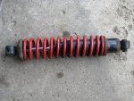
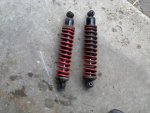
The shocks 13.5" eye to eye. They're old but with more than enough life in them for my use.

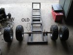
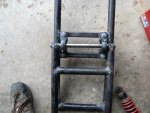
The attached swing arm

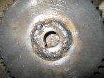
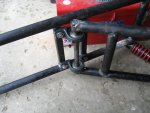
A close up of how the swing arm at attaches. I still need to drill and pin the joints.

Just another pic of it attached. This will most likely be the normal driving position of the swing arm with another inch before full droop.

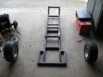
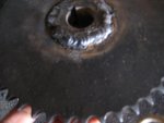
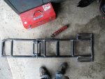
The bottom of the frame.

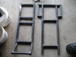
Another close up. See the gaps? I'm making spacers to take up the space.


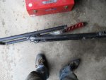
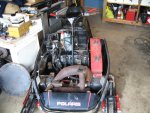
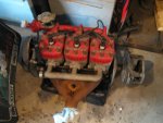
The donor sled along with the engine (indy 650. picked it up for $150, runs but needs lots of work but very little money put into it. It has 97hp stock and upwards of 120hp piped:arf:. Still looking for a set of triple pipes for it.) I was going to use the engine for a larger buggy build but my dad put an end to that by not letting me use the truck to pick it up if i was going to use the engine in my buggy, so i have to keep it as a seld ;).

A blurry pic of the shocks. The top one is one of the new shocks for the front and the bottom was the current shock.
 

Attachments

  • IMG_5079.jpg
    IMG_5079.jpg
    80.1 KB · Views: 236
  • IMG_5078.jpg
    IMG_5078.jpg
    91.7 KB · Views: 235
  • IMG_5077.jpg
    IMG_5077.jpg
    94.5 KB · Views: 232
  • IMG_5076.jpg
    IMG_5076.jpg
    122.3 KB · Views: 233
  • IMG_5075.jpg
    IMG_5075.jpg
    104.4 KB · Views: 235
  • IMG_5080.jpg
    IMG_5080.jpg
    98.8 KB · Views: 231
  • IMG_5081.jpg
    IMG_5081.jpg
    112.8 KB · Views: 226
  • IMG_5083.jpg
    IMG_5083.jpg
    118.4 KB · Views: 235
  • IMG_5084.jpg
    IMG_5084.jpg
    80.7 KB · Views: 232
  • IMG_5086.jpg
    IMG_5086.jpg
    71 KB · Views: 225
Status
Not open for further replies.
Top