I need help: Wiring and electrical components

Status
Not open for further replies.

KartFab

Active member
Messages
3,381
Reaction score
57
Location
Dallas, TX
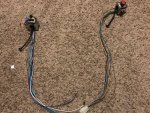
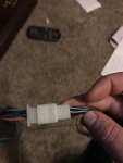
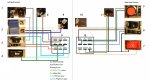
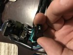
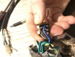
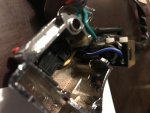
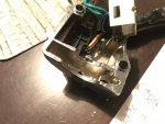
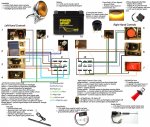
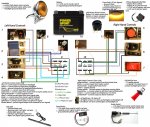
Hey all, i bought some 7/8" "chrome" hand controls for a mini bike. They are from china, and of course, no instructions available. I spent a while tracing all the wires back to the individual switches, and there are no "electrical components" e.g. relays built into the switches. I made this diagram and it looks like the connectors for LH/RH actually may plug into each other, and none of the colors match up if they do plug into each other.

Im trying to figure out which ones are ground, and which ones should go to additional components I need to wire, and what all the symbols mean. I have numbered each component and would appreciate an explanation if possible. Some of the stuff i understand, but some of the stuff i am a little confused on.

I am hoping to be able to use this diagram to figure out which relays i need to purchase so i can get the following wired up and functional

1) hazard lights (plan on using turn signal leds in front/rear for this)
2 )low beam, high beam (already have a 3 wire headlight for this)
3) turn signals for front and rear (plan on using turn signal leds in front/rear for this)
4) horn, already got this, it has a negative and positive
5) engine kill switch, im assuming one is coil wire and one is ground
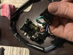
6)no idea what these three symbols are for, it has three switch positions here
7) will not use electric start
8) no idea this was close to the hand control and is a female spade connector
9)lh loom connector do they connect together? white wire? blue wire?
10)rh loom connector do they connect together? brown/white wire?
11) additional female spade connectors,near hand controls.

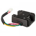
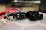
Soooo... wow what a cluster right? I have also purchased a 4-wire, 2 phase regulator rectifier for the tecumseh engine that im putting on the bike as it has 2 wires coming out of that, and i got that down, reg/rec will hook directly to battery. Im thinking i will need an LED compatible signal relay of some sort to get turn signals going and hazards going.

I plan on purchasing red heat shrink and red nylon wire loom and drilling some holes in the handlebars to run it discretely.

This is the biggest electrical endeavor i have taken on and hopefully it will be a learning experience and it will help those that want to do this too..... so can i get some help here explaining items 1 through 11 as to what goes where and what relays, grounds, and hots need to go where etc etc etc.

UPDATE: Found possibly a match for Left Hand control, but not sure of hot/ground on that control. Added to diagram. Female spade connectors for #8 and #11 could be for hand levers like clutch, brake, but not sure.

Here is what I am guessing with polarity
#1unkown
#2 blue/white = to headlight wire (-)
#2 blue = to headlight low beam wire (+)
#2 white = to headlight high beam wire (+)
#3 unknown
#5 black/white = to magneto /coil kill wire
#5 green = to frame or battery ground (-)
#6 unknown
#7 unknown
#8 uknown
#9 unknown
#10 unknown
#11 unknown
 

Attachments

  • thumbnail_IMG_4808.jpg
    thumbnail_IMG_4808.jpg
    473.2 KB · Views: 9
  • thumbnail_IMG_4809.jpg
    thumbnail_IMG_4809.jpg
    140.7 KB · Views: 6
  • Wiring Diagram with labels.jpg
    Wiring Diagram with labels.jpg
    190.8 KB · Views: 34
itsid

Moderator
Staff member
Messages
11,563
Reaction score
245
Location
Ruhrpott [Germany]
let me try to fill in some of that list:

1-5 I consider covered ;)

6) That is yourr light switch.. OFF (dot) position light (the two opposing lights) and ON (lit bulb)

7) will not use electric start (why not?)

8) It's very likely a NO switch from the clutch lever as e-start protection [need to pull the clutch in order to be able to start] fairly common on motorcycles these days (disabled mine)

9) lh loom connector do they connect together? white wire? blue wire?
NOPE, but the striped white/blue one should, in order to split the "headlights on" into "low" or "hi" beam ;)

10) rh loom connector do they connect together? brown/white wire?
NOPE they don't

11) That one is tricky.. "side stand out" is a common signal,
in which case it actually shortens the kill switch as soon as the neutral light goes out,
another possibility is it's preventing to start an already running engine ...
or something I didn't think of yet :(


Also.. keep in mind that these are switches.. they're NOT plus an minus in terms of voltage,
they split or connect either of those (so NEVER run +12 and ground to the switches!)
chances are the rh-control dark green is your only ground
(otherwise coloring conventions call for black...)
Let me check my controls wiring diagram to get a better grip *giggle*
and maybe add or alter some statements :D


Sellers on ebay/amazon usually point to a specific bike or scooter in order to advertise their stuff,
maybe we can derive missing and verify existing infos from that respective wiring diagram..

So mind to point us to the source, or check again for some bike model?

'sid
 

KartFab

Active member
Messages
3,381
Reaction score
57
Location
Dallas, TX
Ok so heres an update on the list, what do you all think? You can substitite battery+ to keyed+ if i put a master key switch on battery+

#1hazards: gray goes to battery +, flip switch provides + current to brown/white, and brown white provides + current to both light blue and orange when hazard light is switched on

#2 blue/white = ? (ground or battery +?)
#2 black = ? (ground or battery +?)
#2 blue = provides + current to headlight low beam
#2 white = provides + current to headlight high beam

#3 gray =battery positive (+)
#3 orange = provides + current to left signal
#3 blue = provides + current to right signal

#4= one is battery+ and one is provides + current to horn positive terminal

#5 black/white = to magneto /coil kill wire
#5 green = to frame or battery ground (-)

#6 brown/white =?
#6 brown =?
#6 blue/white =?
#6 black =?

#7 black = battery +
#7 pink/yellow = provides + current to starter solenoid

#8 green = battery +, which would make #4 teal the positive current to horn + terminal
#8 green/red = positive current to aux or light activated by brake or clutch lever?

#9/#10 =dont connect

#11 black = battery +, which would make #6 black and #7 black battery +
#11 green/yellow = positive current to light activated by brake or clutch lever??
 

Attachments

  • IMG_4798.jpg
    IMG_4798.jpg
    181.8 KB · Views: 4
  • IMG_4797.jpg
    IMG_4797.jpg
    175.3 KB · Views: 4
  • IMG_4794.jpg
    IMG_4794.jpg
    203.3 KB · Views: 5
  • IMG_4793.jpg
    IMG_4793.jpg
    195.4 KB · Views: 3
  • IMG_4791.jpg
    IMG_4791.jpg
    237.4 KB · Views: 5

Texan

Senor Member
Messages
461
Reaction score
11
Location
Deep In The Heart of Texas
Green & yellow is your brake switch.

Gray is +Battery coming from flasher relay.

Blue & white is probably you Engine alternator + output to power the lights.
 

itsid

Moderator
Staff member
Messages
11,563
Reaction score
245
Location
Ruhrpott [Germany]
#2 blue/white = ? (ground or battery +?) NEITHER!!
connected to #6 rh-control blue/white


#1 & #3 gray =battery positive (+) again NOPE!
it's the pulsed positive from the turn relay
the brown/white interconnects to run both l and r at the same time.

#6 brown/white = likely position light
#6 brown = likely bat + (key switched if wanted)
#6 blue/white = to #2 blue/white
#6 black = likely bat + (key switched if wanted)
one of the bat + (brown likely) is meant to provide power to the position lights in key-locked position (parking lights) in case you have a three position keyswitch (P_off_on)

the rest I agree ...
well as far as I was able to follow (it's kinda tricky with all the scrolling and reopening the image every other second ;))

'sid
 

KartFab

Active member
Messages
3,381
Reaction score
57
Location
Dallas, TX
UPDATE
how in the world?!?!!? I am finding it hard to believe that the coil puts out AC AND DC power? It is mentioned here in our forum. How do i test for this in a multimeter?
http://www.diygokarts.com/vb/showthread.php?t=22139
did some research here and noticed that it may in fact do that....
https://lookup3.toro.com/ttcGateway/acrobat/manuals/tecqkref.pdf see page 47/48 on the pdf... okay... time to investigate what i actually have.... so im thinking i can just cut off the diode, and wire directly to the regulator/rectifier i bought insteadl?
here is the regulator rectifier i am using
https://www.ebay.com/itm/12V-Quad-B...e=STRK:MEBIDX:IT&_trksid=p2057872.m2749.l2649

I was able to locate the item on ebay, different seller
https://www.ebay.com/itm/Pair-Motor...m=202518865788&_trksid=p2047675.c100752.m1982

ok so with this given information here is the updated list that includes a light flasher relay

3 Pin 12V Electronic Motorcycle ATV Turn Signal LED Light Flasher Blinker Relay
Red lead is connected to positive pole of power supply. Green lead is connected to positive pole of turn signal indicator. Black lead is connected to negative pole of power supply.

So this means green wire on relay goes to GRAY on LH control. so, making that change in the list, and the others, we are now currently sitting here with my THOUGHTS (knowing i am probably still wrong with a few of the items):

Hand Controls

You can substitite battery+ to keyed+ if i put a master key switch on battery+

#1 hazards: gray goes to (flasher relay green +), flip switch provides + flasher relay current to brown/white, and brown white provides + flasher relay current to both light blue and orange when hazard light is switched on

#2 blue/white = receiving + current from #6 blue/white +
#2 black = headlight ground
#2 blue = provides + current to headlight low beam
#2 white = provides + current to headlight high beam

#3 gray = receives flasher relay green +
#3 orange = provides + flasher relay current to left signal
#3 blue = provides + flasher relay current to right signal

#4 green= battery+
#4 teal= provides positive current to horn positive terminal

#5 black/white = to magneto /coil kill wire
#5 green = to frame or battery ground (-)

#6 brown/white = provides + current to the "lightbulb" turns on lets say some LED ground effects?
#6 brown = ground
#6 blue/white = provides current to headlight switch #2, as well as the "two" small running lights/side markers/position lights
#6 black = battery +

#7 black = battery +
#7 pink/yellow = provides + current to starter solenoid

#8 green = battery +,
#8 green/red = positive current to aux or light activated by brake or clutch lever?

#9/#10 =dont connect

#11 black = battery +
#11 green/yellow = positive current to brake switch


Also, any ideas on what gauge wire i should buy to do my wire runs? not sure what gauge this stuff is.

flasher relay can support up to 250 watts total @12v
https://www.ebay.com/itm/3-Pin-12V-...-LED-Light-Flasher-Blinker-Relay/312141039187

headlight is an H4 bulb at 12 v so, 60watts high, 55 watts low
https://www.ebay.com/itm/Motorcycle...e:g:8FMAAOSwySVaJspB:rk:3:pf:1&frcectupt=true

using this infor for H4 bulbs
http://www.run-n-lites.com/prod-Halogen&Xenon.html

Which leaves me with options for side indicator (position/running) lights beyond the headlight, turn signal lights, brake lights, and ground effects lights.

I also have a universal brake light switch which i will tie into battery/switch+ as this is a simple brake, and not hand controlled (e.g. friction scrub brake on lever by foot peg)
https://www.ebay.com/itm/UNIVERSAL-...h=item5d6fd09096:g:vXcAAOSwc-tY76ub:rk:9:pf:0

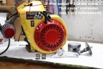
I will have to see how much power output i can maintain, but im just taking a very simple 3 amp hour 12v battery, and running it off the charge coil, which seems to be a fairly substantial coil. it is the full circle coil with two output wires, so i am thinking it will be a minimum of 6 amps and possible ten, but i am unsure, i think it could put out just 3 amps minimum so that is where i think it could be.

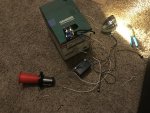
Once we get the list hashed out, I will be BRAVE enough to pull out my miltimeter and some lights to really test things off of the mini bike (e.g. headlight, turn signals, side indicator etc). Ill go ahead and order this relay as i have to get that no matter what.
 

Attachments

  • s-l500.jpg
    s-l500.jpg
    27.9 KB · Views: 5
  • 2 phase reg rec.jpg
    2 phase reg rec.jpg
    22.6 KB · Views: 4
  • 49348877_10156294986522933_8161939318542172160_o.jpg
    49348877_10156294986522933_8161939318542172160_o.jpg
    259.1 KB · Views: 6

KartFab

Active member
Messages
3,381
Reaction score
57
Location
Dallas, TX
Left Hand Control: Tested and CONFIRMED!!!
#1 hazards: gray goes to (flasher relay green +), flip switch provides + flasher relay current to brown/white, and brown white provides + flasher relay current to both light blue and orange when hazard light is switched on

#2 blue/white = receiving + current from #6 blue/white +
#2 black = headlight ground
#2 blue = provides + current to headlight low beam
#2 white = provides + current to headlight high beam

#3 gray = receives flasher relay green +
#3 orange = provides + flasher relay current to left signal
#3 blue = provides + flasher relay current to right signal

#4 green= battery+
#4 teal= provides positive current to horn positive terminal
 

Attachments

  • 1648E8DD-8B6B-4547-98F0-3BFF22109171.jpg
    1648E8DD-8B6B-4547-98F0-3BFF22109171.jpg
    462.6 KB · Views: 2

KartFab

Active member
Messages
3,381
Reaction score
57
Location
Dallas, TX
Right Hand:

#5 obvious the way it is wired but have not tested, should be ok

#6 Tested and "Sparky" haha, spark made when just brushing wire over battery terminal to see if we have continuity instead of using a multi-meter.

here are three sparky switch combinations, based on these combinations we get the following:

black +,
brown -
dot =nothing
running lights=spark
bulb=spark

black +
blue/white -
dot =nothing
running lights=nothing
bulb=spark

black +
brown/white -
dot= nothing
running lights=spark
bulb=nothing

To me nothing=no connection, spark=continuity. After the process of elimination.

dot position is off, no continuity between black and any wire, check
running lights position, continuity between brown/white, and brown, no blue white continuity
light bulb position continuity between brown, and blue/white, no brown/white continuity

To me this means,
none of the wires coming out of #6 are ground wires

brown/white are sidemarkers light 1 on only
blue/white are light 2 on only
brown are light at both positions.

With that said, what should light 1 and light 2 and both positions be? Ive got some choices now with #6

My Thoughts Now For RH Control #6:
BROWN=+ out to headlight#2 control (blue/white) and + out to tail light
BROWN/WHITE = side markers or fog lights or daytime running lights or wahtever
BLUE/WHITE = led underglow with sidemarkers off, but headlight and tail light still on.

What do you all think? Now i just need to figure out what turn signal lights, underglow, and brake/tail lights to get that will look good on the manco thunderbird
 

itsid

Moderator
Staff member
Messages
11,563
Reaction score
245
Location
Ruhrpott [Germany]
sparky is no good indicator..
in fact it's even a bad test!
Anyways that makes no sense at all

for two reasons.
A) the light switch has TWO plus 12 V connections (at least mine has on my Suzuki GSXR)
ones exclusively for the head lights, the other exclusively for the position lights
in "ON" position (lightbulb) both are conencted to it's respective relative
in "S" position (the opposing lights symbol) only the position lights are connected, the other pair stays off

and
B) The position lights are always lit even if the headlights are on.. so it cannot be either ;)

SO my thinking is:
black is the 12V for headlight (since it's also on the starter button) and brown for the position lights. (black being keyed, brown being permanent +12V)

That way black and brown would essentially be BOTH 12V+
and it'd run like that:

keyswitch off:
dot : all off
runninglights: position lights on, headlights off
bulb: position lights on, hadlights off

keyswitch on:
dot: all off
runninglights: position lights on, headlights off
bulb: position lights on, headlights on

blue/white is surely the interconnection between lh and rh control...
everything else just doesn't make the slightest sense!

'sid

PS So yeah, get a multimeter out and test for continuity (all lines at all switch positions)
draw a table (switch pos as rows, and all colors as columns) and then connect the dots in the grid
for all three positions.
 

KartFab

Active member
Messages
3,381
Reaction score
57
Location
Dallas, TX
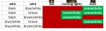
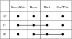
okay here is what we got for switch #6
Untitled-2.jpg

and here is what i have for lights (so far)
front/rear turn signals
headlight/hi/lo
brake light
tail light

I have no experience on lights, so i have no idea which should run at what key position and what switch position.

I have been ignoring the master or key switch long enough, and now it is time to think about that for me.

So are we in agreement that brake light and side indicator lights should be dedicated 12v, and the remainder of all lights and accessories should be keyed 12v?
 

KartFab

Active member
Messages
3,381
Reaction score
57
Location
Dallas, TX
Draft Wiring Diagram all accessories included.

I do not intend to have any hots un-switched at this time. One switch to rule them all.

No immediate plans for LED underglows yet, but that can be easily added to master switch with remote or an existing switch.

Some info was pulled from this Honda wiring color code site to fill in LH/RH controls
http://www.vsource.org/VFR-RVF_files/HondaWireColors.htm
 

Attachments

  • one ring to rule them all.jpg
    one ring to rule them all.jpg
    911.4 KB · Views: 3
  • Wiring Diagram.jpg
    Wiring Diagram.jpg
    470.3 KB · Views: 6

itsid

Moderator
Staff member
Messages
11,563
Reaction score
245
Location
Ruhrpott [Germany]
So according to your table up there the
conenctions are as follows:
switch_six.png

Why is that a better table? you might ask..
well it's what mfgs use in their wiring diagrams
for two very important reasons..
it attaches nicely to such wiring diagram (every wire could drop off a column and feed into the drawn rat's nest)
AND it opens up some internal logic.

Like: it makes no sense to interconnect both +12V lines
since that would always power the "keyed power" line without the key and make it obsolete..

So either brown or black is not a 12V line..
since with the starter switch we know black must be.. that leaves brown to "can no longer be a +12V"

frankly that diagram itself doesn't make much sense
I expected two seperate connecions to be frank
(like brown and brown/white on one side for running lights and black and blue/white on the other side for head lights)
distinct pairs..
a three wire interconnection isn't of much use if we assume two distinct power lines for keyed and unkeyed power.
(since that config would put power on the starter button without the key again no matter how it's set up)

because of that I assume
there's either some fault in that schematic,
or we went off the wrong assumptions in the first place....

maybe parking lights and position lights are not expected to be the same thing with this switch (like powering the left turn indicator as a parking light? which isnt too uncommon)
but that'd make brown/white the parking light
and brown the position light
which then would make sense to be named as you do as "running lights"
BUT usually that includes the tach backlight and also running lights (as far as I understand) include a tail light light up.. making the turn indictator light obsolete...
*sigh* brown and black make no sense to me...

IDK
I understand that you're unwilling to test the switch again,
but in order to know for sure, a good diagram is the only thing that helps I'm afraid.

that would need to be done for all the switches and toggles (and even indicator lights if there are any)
and yes.. I know that involves some work..
carefully probing all leads at all posssible positions (of all included switches) and even some shifting around of the columns in order
to make the interconnection lines as short as possible.

The good thing is... if you cannot match up the lines to a plausible arrangement,
there must be a flaw in your measurements (slipped probe)

'sid
 

KartFab

Active member
Messages
3,381
Reaction score
57
Location
Dallas, TX
Alex,

Not sure what i messed up on but here it is as i wired it up per the diagram tested with all connections that i currently have.

brown and blue/white will never actually be connected at that switch position, even though they have continuity between them at that position. That threw me off as well. They just both provide 12v from the same source at that position.

until i get the rest of the items, the only three hots coming from 12v source are
  • Left hand control gray blinkers
  • Left hand control horn
  • Right hand control black supplies #6 switch


https://youtu.be/VWFMqOxqoCY
 

Attachments

  • Wiring Diagram.jpg
    Wiring Diagram.jpg
    474.2 KB · Views: 5

KartFab

Active member
Messages
3,381
Reaction score
57
Location
Dallas, TX
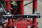
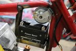
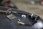
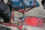
Here are some pictures of my progress to make up for all the typing from this thread.
 

Attachments

  • IMG_0868.jpg
    IMG_0868.jpg
    201.6 KB · Views: 1
  • IMG_0845.jpg
    IMG_0845.jpg
    292 KB · Views: 1
  • IMG_0843.jpg
    IMG_0843.jpg
    212.1 KB · Views: 1
  • IMG_0822.jpg
    IMG_0822.jpg
    279.7 KB · Views: 1
  • IMG_0824.jpg
    IMG_0824.jpg
    259.7 KB · Views: 1
  • IMG_0878.jpg
    IMG_0878.jpg
    231.6 KB · Views: 1
  • IMG_0891.jpg
    IMG_0891.jpg
    264 KB · Views: 1
  • IMG_0898.jpg
    IMG_0898.jpg
    164.3 KB · Views: 1
  • IMG_0920.jpg
    IMG_0920.jpg
    158.8 KB · Views: 1
  • IMG_0926.jpg
    IMG_0926.jpg
    170.3 KB · Views: 1
Status
Not open for further replies.
Top