KartFab
Active member
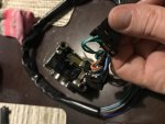
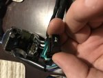
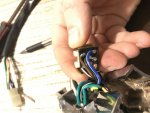
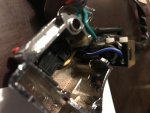
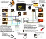
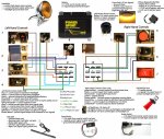
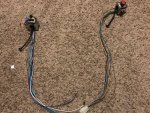
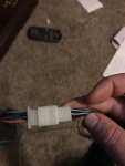
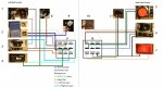
Hey all, i bought some 7/8" "chrome" hand controls for a mini bike. They are from china, and of course, no instructions available. I spent a while tracing all the wires back to the individual switches, and there are no "electrical components" e.g. relays built into the switches. I made this diagram and it looks like the connectors for LH/RH actually may plug into each other, and none of the colors match up if they do plug into each other.
Im trying to figure out which ones are ground, and which ones should go to additional components I need to wire, and what all the symbols mean. I have numbered each component and would appreciate an explanation if possible. Some of the stuff i understand, but some of the stuff i am a little confused on.
I am hoping to be able to use this diagram to figure out which relays i need to purchase so i can get the following wired up and functional
1) hazard lights (plan on using turn signal leds in front/rear for this)
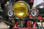
2 )low beam, high beam (already have a 3 wire headlight for this)
3) turn signals for front and rear (plan on using turn signal leds in front/rear for this)
4) horn, already got this, it has a negative and positive
5) engine kill switch, im assuming one is coil wire and one is ground
6)no idea what these three symbols are for, it has three switch positions here
7) will not use electric start
8) no idea this was close to the hand control and is a female spade connector
9)lh loom connector do they connect together? white wire? blue wire?
10)rh loom connector do they connect together? brown/white wire?
11) additional female spade connectors,near hand controls.
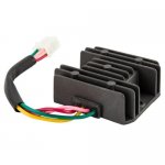
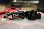
Soooo... wow what a cluster right? I have also purchased a 4-wire, 2 phase regulator rectifier for the tecumseh engine that im putting on the bike as it has 2 wires coming out of that, and i got that down, reg/rec will hook directly to battery. Im thinking i will need an LED compatible signal relay of some sort to get turn signals going and hazards going.
I plan on purchasing red heat shrink and red nylon wire loom and drilling some holes in the handlebars to run it discretely.
This is the biggest electrical endeavor i have taken on and hopefully it will be a learning experience and it will help those that want to do this too..... so can i get some help here explaining items 1 through 11 as to what goes where and what relays, grounds, and hots need to go where etc etc etc.
UPDATE: Found possibly a match for Left Hand control, but not sure of hot/ground on that control. Added to diagram. Female spade connectors for #8 and #11 could be for hand levers like clutch, brake, but not sure.
Here is what I am guessing with polarity
#1unkown
#2 blue/white = to headlight wire (-)
#2 blue = to headlight low beam wire (+)
#2 white = to headlight high beam wire (+)
#3 unknown
#5 black/white = to magneto /coil kill wire
#5 green = to frame or battery ground (-)
#6 unknown
#7 unknown
#8 uknown
#9 unknown
#10 unknown
#11 unknown
Im trying to figure out which ones are ground, and which ones should go to additional components I need to wire, and what all the symbols mean. I have numbered each component and would appreciate an explanation if possible. Some of the stuff i understand, but some of the stuff i am a little confused on.
I am hoping to be able to use this diagram to figure out which relays i need to purchase so i can get the following wired up and functional
1) hazard lights (plan on using turn signal leds in front/rear for this)
2 )low beam, high beam (already have a 3 wire headlight for this)
3) turn signals for front and rear (plan on using turn signal leds in front/rear for this)
4) horn, already got this, it has a negative and positive
5) engine kill switch, im assuming one is coil wire and one is ground
6)no idea what these three symbols are for, it has three switch positions here
7) will not use electric start
8) no idea this was close to the hand control and is a female spade connector
9)lh loom connector do they connect together? white wire? blue wire?
10)rh loom connector do they connect together? brown/white wire?
11) additional female spade connectors,near hand controls.
Soooo... wow what a cluster right? I have also purchased a 4-wire, 2 phase regulator rectifier for the tecumseh engine that im putting on the bike as it has 2 wires coming out of that, and i got that down, reg/rec will hook directly to battery. Im thinking i will need an LED compatible signal relay of some sort to get turn signals going and hazards going.
I plan on purchasing red heat shrink and red nylon wire loom and drilling some holes in the handlebars to run it discretely.
This is the biggest electrical endeavor i have taken on and hopefully it will be a learning experience and it will help those that want to do this too..... so can i get some help here explaining items 1 through 11 as to what goes where and what relays, grounds, and hots need to go where etc etc etc.
UPDATE: Found possibly a match for Left Hand control, but not sure of hot/ground on that control. Added to diagram. Female spade connectors for #8 and #11 could be for hand levers like clutch, brake, but not sure.
Here is what I am guessing with polarity
#1unkown
#2 blue/white = to headlight wire (-)
#2 blue = to headlight low beam wire (+)
#2 white = to headlight high beam wire (+)
#3 unknown
#5 black/white = to magneto /coil kill wire
#5 green = to frame or battery ground (-)
#6 unknown
#7 unknown
#8 uknown
#9 unknown
#10 unknown
#11 unknown
Attachments
-
 thumbnail_IMG_4808.jpg473.2 KB · Views: 9
 -
 thumbnail_IMG_4809.jpg140.7 KB · Views: 6
 -
 Wiring Diagram with labels.jpg190.8 KB · Views: 34