I finally bit the bullet

Status
Not open for further replies.

Tpdingo

Member
Messages
902
Reaction score
8
Location
Bellmore, NY
Hey you said it was dynomite, I don't see anything exploding? This ain't a real dyno without something exploding :lolgoku:

That looks like a kickass stand you got there!
 

KartFab

Active member
Messages
3,381
Reaction score
55
Location
Dallas, TX
Got word back about the torque arm stop. There needs to be some play in the space between the torque arm and the torque arm stop. This will avoid dealing with torque hysteresis.

www.dynomitedynamometer.com/dyno-tech-talk/torque_hysteresis.htm

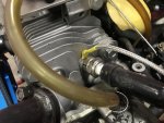
Don’t get HOSED… by that final plumbing connection between your DYNOmite absorber and its supply, drain, and vent hoses!!!! This is too easy a spot to inadvertently induce measurable torque errors! You need to carefully select each hose’s routing.

Because it’s so simple to “Zero” out minor torque offsets, even many experienced dyno operators get complacent about monitoring for errors - that hose weight and stiffness might be adding. Next time you test, take a few seconds to examine how your own lines are attached.

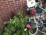
Press lightly (one finger) on the o.d. of the absorber housing - rotating it enough to just move the Torque reading. Then let go. If the gauges do not return, your hose routing is probably too stiff (adding torque latency and hysteresis). Try re-arranging them. Hoses that exit straight for several inches (before any bends or tie wraps) are much less prone to inducing rotational loads.

Next, open the load valve to fill up the hoses with water. Does the added weight and flow move the torque? If so, you have some more work to do. Again, avoid hose bends near the absorber that amplify the rotational leverage of the hose’s weight.

It’s often practical to replace a long drain hose with just a short hose stub - that squirts into an adjacent “catch stand” drain pipe. This trick provides a “sticktion” free junction (that can be used for the vent line as well). Just be sure that its “spray angle” is not at all tangential to the absorber’s o.d. to avoid inducing any torque reaction (from this high velocity water jet).

When things are plumbed correctly - torque readings and zeroing are more consistent, plus, inertial compensation stays in phase with measured torque. In other words, you get more accurate results...more easily!
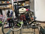
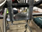
So after reading this, I messed with the hoses a bit and made sure they were all "straight out" from the water brake so they dont put any leverage on the torque arm. Looking at 'worst case' by forcing the supply "in" and "out" hose to go not straight, it was potentially introducing a reading of about 0.1 ft/lbs. When it was straight, or untouched, then the hose didn't really show any error on the reading.

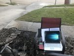
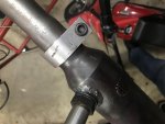
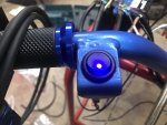
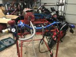
Got the old handlebars off my Manco thunderbird minibike. For load control on the left and throttle control on the right.

Still got to weld up a mounting platform for the small computer, wideband sensor, battery mount, and fuel tank. I was tempted to run it tonight, but I’ll have to wait a bit longer.

Im thinking battery box oon the left corner, closest to me in that pic, and some sort of gravity fed fuel tank with enough line to reach an engine. Not sure about placement for that part, considering some sort of adjustable arm that folds down or something like that. Any ideas?
 

Attachments

  • 42F05EDF-79E2-44F6-9952-170B622677A1.jpg
    42F05EDF-79E2-44F6-9952-170B622677A1.jpg
    401.3 KB · Views: 23
  • A2FF195A-0A22-4E4A-B482-2A1744CAD03E.jpg
    A2FF195A-0A22-4E4A-B482-2A1744CAD03E.jpg
    270.8 KB · Views: 16

KartFab

Active member
Messages
3,381
Reaction score
55
Location
Dallas, TX
update: did my first few runs over the weekend. Torque readings are spot on for this engine ~22ish ft/lbs at 10.2:1CR. 50 lb HD valve springs are floating at 4800-5000 rpm with the stock cam. honda gx390 engine

The problem is that the rpm readings on my hand held dyno computer are accurate, but when connected to the laptop, they read half, if that the rpm as the absorber rpm. USER ERROR haha!

Software is extremely complicated but ill get there eventually. So far have just played with the graphs, scales etc. I might actually have to use the absorber rpm at 1:1 ratio... sigh... i did that but the readings are still off....

Also, as a note to anyone thinking about getting a water brake dyno. DONT DO IT haha. The giant flywheel types seem like a better fit for these engines. This engine, overpowers the loading capability of the water brake at low rpms, because that is where all the torque is, peak torque at 2000-2500 rpm? It just blows past that, and if you fully load it, the engine overpowers it but doesnt rev all the way out, SO...., with that said. maybe the small block will play nice with this, but the big block with 22 ft lbs of torque just blows past my loading capabilities, and if i load it hard at idle, it just stalls the engine. It seems like there is a significant lag in loading that the engine just jumps past, then at fully loaded, it wont bring the rpms down to 2k. So we basicallly have an engine that has 18-22 hp (if that), that this water brake advertized to handle 60+hp cannot load. Pathetic really. But who knows, maybe im just frustrated. I wanted this to handle the 10-sh ft lbs of the small blocks, which i havent even tested yet, the 19ish ft lbs of the big blocks which it doesnt handle, and screw this whole 30ish ft lbs of the v twins. I know its not going to load that for sure...

So.... hand loading with the water valve doesnt seem like a good option. Might have to save up more money for the black hole/money pit for auto loading servo. For now, have to wait a few more days for a tech support call to figure out why I'm so technologically challenged. I can build my own computers, build my own engines, etc, but cant figure out where to change the rpm source to the correct source, and have it read what the handheld computer says on my laptop. *sigh*

Prior to all this, the CD installation didnt work, and i had to have tech support just transfer a few files from my CD to the computer. That was easy... so I did the same thing to my laptop because the handheld wouldnt download to my PC. Friggin nightmare. At least they have good tech support. Where I currently sit with this is extremely ****ed off, and the software is anything but intuitive. The help menus are great, and explain a lot, and the users manual they give you is like 5" thick. I read the thing, and it is missing BASIC BASIC wiring diagrams, and BASIC BASIC items that are essential to getting this thing to work. Super frustrating. This dyno software is anything but user friendly and anything but intuitive. Good thing though, is that it isnt running on microsoft DOS haha! At least they have that going for them.

For example, they send you a wiring harness for the engine rpm, and it has a red wire a yellow wire and a black wire. They mention in passing in an obscure section of of the manual that you can wire the yellow wire to the magneto. Ok great. BUT they dont mention anything about the black wire or red wire. Well after calling tech support, the black wire is for ground, and the red is 8 volts out to supply other devices that they use. So if i would have hooked up the red wire to the battery hot, that owuld have been bad. So its just really basic stuff like that, like literally a wiring diagram could have fixed that question.

Dont even get me started on this other crap they are pulling with the software 'lite' vs 'pro' like lite is supposed to be a FREE demo, but no, thats the one that comes with the dyno, and if you want to do some easy math crap like average 3 runs together, nope you gotta buy the $1500 software, and the graphs still look like ****. Im just glad that this will let me export as an CSV/excel sheet so i can do formulas myself, and more importantly make beautiful graphs that dont look like they were made in 1987.

Buyers remorse? Nah. I knew what I was getting into. I just want my **** to work and I am too picky with the graphs. I already have an excel format that i do for my real job that i modified that will make some beautiful graphs. Cant wait to show it off when i finally get to the point where i can make all this come together.
 

65ShelbyClone

Active member
Messages
669
Reaction score
163
Location
SoCal
It seems like there is a significant lag in loading that the engine just jumps past, then at fully loaded, it wont bring the rpms down to 2k. So we basicallly have an engine that has 18-22 hp (if that), that this water brake advertized to handle 60+hp cannot load. Pathetic really. But who knows, maybe im just frustrated. I wanted this to handle the 10-sh ft lbs of the small blocks, which i havent even tested yet, the 19ish ft lbs of the big blocks which it doesnt handle, and screw this whole 30ish ft lbs of the v twins. I know its not going to load that for sure...

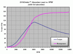
Land & Sea's 5" water brake needs to be at 3000rpm or more to control the engine at that output. It might require overdriving the absorber, which would unfortunately mean the extra work of putting it on a trunnion. Cheaper than upgrading to the 7" brake though.

https://www.dynomitedynamometer.com/absorber/dynamometer-absorbers-load-charts.htm

The lag seems to be a nuance of water brakes in particular. Every academic discussion I've read about them mentions it in some form. It has to do with the mechanics of how quickly the brake can fill and drain water. Applications that need a fast-acting brake typically employ eddy current absorbers. They come at the cost of more weight, more inertia, and lower sustainable power ratings for the size.
 

Attachments

  • 5_absorber_rpm_vs_load_chart.gif
    5_absorber_rpm_vs_load_chart.gif
    16.2 KB · Views: 3

KartFab

Active member
Messages
3,381
Reaction score
55
Location
Dallas, TX
Land & Sea's 5" water brake needs to be at 3000rpm or more to control the engine at that output. It might require overdriving the absorber, which would unfortunately mean the extra work of putting it on a trunnion. Cheaper than upgrading to the 7" brake though.

https://www.dynomitedynamometer.com/absorber/dynamometer-absorbers-load-charts.htm

The lag seems to be a nuance of water brakes in particular. Every academic discussion I've read about them mentions it in some form. It has to do with the mechanics of how quickly the brake can fill and drain water. Applications that need a fast-acting brake typically employ eddy current absorbers. They come at the cost of more weight, more inertia, and lower sustainable power ratings for the size.

I have the 7" 'high torque' rotor
 

Attachments

  • 7_absorber_rpm_vs_load_chart.gif
    7_absorber_rpm_vs_load_chart.gif
    16.3 KB · Views: 7

65ShelbyClone

Active member
Messages
669
Reaction score
163
Location
SoCal
Oh, I see. Have you tried different drain orifices? The slow response and poor loading you mentioned suggests to me that it could be a water flow issue, either in or out.

Just throwing ideas out there; their tech support will be more helpful.
 

KartFab

Active member
Messages
3,381
Reaction score
55
Location
Dallas, TX
First Sucessful test

so i had to mess around with the settings for about an hour, and i got the engine rpm off of the kill switch wire instead of the absorber.

Hooked up the dyno on the front of the house instead of the rear, and lo and behold at almost freezing temps i can load the engine at full rpm and bring the rpm down. Funny thing is is that the static pressure was the same, 65 psi, and the dynamic pressure was the same 25 psi.

Ran out of what little gas i had left so this is on T4 gas.

Engine is a stock honda gx390 with 50 lb springs and stock cam. Stage 1 upgrades. 10.2:1 compression ratio IIRC.

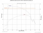
Still trying to figure out graphing capabilities, but am super bummed about the fact that my version does not allow CSV exporting, so no beautiful graphs, just these crappy ones.

Trying to get the peak torque rpm and peak hp rpm to display on graph.

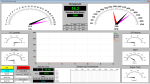
If you look at the screenshot, with torque on the left, you can see peak torque was just over 23 ft pounds (magenta arrow on torque). This peak occurred at approximately 2300 rpm.

Looking at peak hp, this occurred at just shy of 4000 rpm, and is displayed on the graph lower right hand corner.

So that gives me enough confidence to make a few legitimate pulls this week of what i have had in mind for over a year now. Stay tuned! Sorry, we are sticking with the CRAP GRAPHS until i have enough funds to bend over and let these guys give it to me just so i can export a stupid CSV.

Also, look at how far that water shot out! hahaha
 

Attachments

  • Untitled.png
    Untitled.png
    94.3 KB · Views: 15
  • test.jpg
    test.jpg
    155.6 KB · Views: 18
  • IMG_4078.jpg
    IMG_4078.jpg
    527.5 KB · Views: 10
  • IMG_4079.jpg
    IMG_4079.jpg
    477.7 KB · Views: 11

65ShelbyClone

Active member
Messages
669
Reaction score
163
Location
SoCal
Still trying to figure out graphing capabilities, but am super bummed about the fact that my version does not allow CSV exporting, so no beautiful graphs, just these crappy ones.

Does it save the run in a file of some other kind, or does it only create a visual graph? I bet there's a workaround...
 

KartFab

Active member
Messages
3,381
Reaction score
55
Location
Dallas, TX
workaround complete :bannana: didnt even have to type anything.

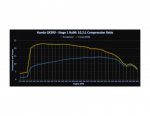
This will help a LOT with the autometer A/F gauge that I have. Ill worry about that down the line, but now I have a way to get that data to work. When speaking with tech support, they basically said, well since you have an air fuel meter that isnt a dynomax meter, you will have to buy the pro version so you can edit the formula for the meter to display the correct lambda/ A/F etc... screw that. Now that i can do the workaround, ill just have the 0-5v channel logged as a column on the table, and at each 100 rpm increase it will have a value, then i can edit/formula whatever i need to do in excel and make it look pretty and be accurate, convert to lambda, gas, whatever.

Better yet, i can compare runs on the same graph (e.g. stock vs stage 1), which im pretty sure these dynomax guys thought would be handy for 'pros' only instead of pee-on "lites" like myself. Havent decided on the final graph layout but it may end up something like this.
 

Attachments

  • Book1.jpg
    Book1.jpg
    147.3 KB · Views: 15

65ShelbyClone

Active member
Messages
669
Reaction score
163
Location
SoCal
When speaking with tech support, they basically said, well since you have an air fuel meter that isnt a dynomax meter, you will have to buy the pro version so you can edit the formula for the meter to display the correct lambda/ A/F etc... screw that.

Yes, screw that. There are many ways to bypass that limitation. One is to use a WBO2 controller with programmable output (like all the common Innovate stuff that I use) and tweak the output curve so the controller and dyno software agree. Even then, if the DAQ is spitting out data in a generic format, it only has to get dumped into Excel and run through a formula like you did. Excel can even collect values directly from a COM port with some simple VB code, technically making their software unnecessary for data collection.

That said, I find that most engine builders below the higher levels are not comfortable nor experienced with the inner workings of software and electronics....or even math and spreadsheets. It's an opportunity for Land & Sea to make some easy money by doing it for them.
 

KartFab

Active member
Messages
3,381
Reaction score
55
Location
Dallas, TX
Predator STage 4 Dyno Numbers

Update: It has been a very long two days of testing and doing other work. But I was able to get a LOT of data, most of it garbage because of the way i was doing the pulls (data recorded when not at full throttle-skewing results low in the graphs). HOWEVER today, I was able to do three runs on my little predator stage 4 build. The engine is a bit peaky past 5500 rpm all the way up until it floats valves at 7800 rpm. I actually need to do a more specific correction factor for my engine's inertia, and i think it will smooth things out even more. I am using the default for "4 cycle 1 cylinder 200+cc "

So, more technical stuff on the way!
https://www.dynomitedynamometer.com/dyno-tech-talk/determining_inertia.htm

But for now, here are the preliminary results of my predator stage 4 build. Everybody loves graphs, so here is one of three back to back pulls, 01 is the first one, and i think it made more hp because the engine wasnt so hot. It gets super hot after a pull and i really didnt let it cool down.

I am trying to figure out best practices for runs. Engine info: got it, Weather: got it: Inertia: almost got it, but pretty close. But some things i think about are, to be most consistent, you would need to get the engine up to temp, so i have this cheap IR laser thermometer, and will probably use that as my guide. Not sure what else to use, other than a legit head temp sensor/tach combo.

I have also come to the conclusion that an inertia dyno and a water brake "should" read the same, but often times they dont. I might be getting a 7.5-8.3 hp reading, when an inertia dyno person says 10 hp.... hmnmmm not adding up... I can actually hook up an inerta dyno to my computer and all i need is engine rpm and flywheel rpm, which i can easily get with a little magnet. I am seriously considering this :idea2:

Anyhow. Thats it for now. Im tired and frustrated. But overall satisfied with the initial results. The below link is a good read, especially the last 5 or 6 sentences sum up how I feel right now.

http://www.carlsonmotorsports.com/CRETechFeb.html

Engine Specs
Head Honda gx160 18cc UT2 head fully ported w/ss valves 27mm in/24mm ex., 3 angle valve job, milled .030" approx 15.3cc
.045" fire ring head gasket
wiseco 3 ring piston for 2.815" bore
billet long rod with wiseco piston puts wiseco at TDC)
balanced rotating assembly
280 0611 cam
black venom 1.3 ratio rockers
cut to length chromemoly pushrods
billet flywheel, set at 32 DBTDC
billet lifters
pull start
probably around 12:1 CR
probably around 216cc
I feel like i need to put a 310 cam in with a big valve head and then i would be satisfied. The short block can handle it.
I think that these numbers are pretty good. I also think that this engine would be 'makin 23-25 hp' on an inertia dyno.:idea2::roflol:

Running out of time to do a lot more R&D, but Ive got big plans and want to have consistent, repeatable results that anybody that doesn't cheat will believe is accurate. I have no reason to inflate numbers because i don't build engines for a living. This is a fun hobby for me, and i like this type of thing.

I did this run with an RLV muffler on and a different header. Cant wait to try out my open long 2 stage header, but that will have to wait.
 

Attachments

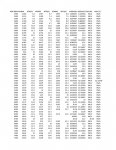
  • KartFab 3 Sweep AVG Data Table.jpg
    KartFab 3 Sweep AVG Data Table.jpg
    406.6 KB · Views: 16
  • KartFab 3 Sweep AVG GRAPH All Displayed.jpg
    KartFab 3 Sweep AVG GRAPH All Displayed.jpg
    164.9 KB · Views: 27
  • KartFab 3 Sweep AVG GRAPH.jpg
    KartFab 3 Sweep AVG GRAPH.jpg
    147.6 KB · Views: 32

65ShelbyClone

Active member
Messages
669
Reaction score
163
Location
SoCal
But some things i think about are, to be most consistent, you would need to get the engine up to temp, so i have this cheap IR laser thermometer, and will probably use that as my guide. Not sure what else to use, other than a legit head temp sensor/tach combo.

For accurate temperature, I love my Fluke 52 II dual thermocouple display.

I have also come to the conclusion that an inertia dyno and a water brake "should" read the same, but often times they dont. I might be getting a 7.5-8.3 hp reading, when an inertia dyno person says 10 hp.... hmnmmm not adding up... I can actually hook up an inerta dyno to my computer and all i need is engine rpm and flywheel rpm, which i can easily get with a little magnet. I am seriously considering this :idea2:

Brake dynos are notoriously unkind (honest?) to power numbers.

It's possible to use a torque arm on an inertia dyno with a little ingenuity and fabrication to make a sort of hybrid dyno.

I did this run with an RLV muffler on and a different header.

I look at those things and can't imagine they flow worth a darn.
 

KartFab

Active member
Messages
3,381
Reaction score
55
Location
Dallas, TX
welp, i got some tentative results back for stage 1, stage 2 and of course, my stage 4 stuff. RLV muffler has two types of mufflers. The ones i was testing with are the punched mufflers, then there are some other ones that have a more of a wire grate on them that are less restrictive. I was testing the punched ones and have not tested the grate ones.

Also, i think i will start with a 3600 rpm and up curve to avoid any data errors. With the way my waterbrake works, there is less inertia with a light flywheel and whatnot, and the engine lugs down and craps out sometimes cant hold it under 3k rpm with a very light flywheel without it stalling quickly. The stock engines with a heavy flywheel can lug down better since they have more inertia. Just to keep things consistent between them all 3600 and up rpm will be good. That might be why the old briggs 5 hp guide started at peak hp 3600 rpm and showed only numbers from there up. Who knows. A lot of dyno people start anywehre form 3000-3600 rpm on their graphs too because different dynos get clutches that wont lock up until 2500 so some of the data will just be lost below 3600 rpm for the sake of these tests. Results are surprising, but clear. will have to wait on data
 

bob58o

SuckSqueezeBangBlow
Messages
9,646
Reaction score
1,833
Location
Chicago-town USA
RLV muffler has two types of mufflers. The ones i was testing with are the punched mufflers, then there are some other ones that have a more of a wire grate on them that are less restrictive.
This is the RLV for Open / Modified's
https://www.arcracing.com/rlv-4106-muffler-open-modified-1-5-16/

This is the RLV for Stock / Builders Prepared
https://www.arcracing.com/dj-1139-rlv-stock-1-5-16-muffler-bp/

I'd be interested in seeing the difference in HP between the two.
 

KartFab

Active member
Messages
3,381
Reaction score
55
Location
Dallas, TX
Update:

No surprise here, but inertia dynamometers read different numbers than water brake dynamometers. Wont go into the reasons why for now, just lost a lot of sleep and sanity researching why my numbers weren't adding up to what I expected them to be. Talked to a few engine builders and the guy that 'makes' the inertia dynos and still ran into some dead ends. I currently believe that a brake dyno will give a "continuous output" or steady state horsepower, which is completely independent of inertia. Since this is also measured at the engine shaft, the numbers you would expect the engine to throw out should be "higher" than what you would expect at the axle or rear wheel. However, the opposite is true in the rabbit hole that I am diving down into. I also believe that inertia dynamometers give "inertial horsepower" or horsepower that the axle or rear wheel will experience, which gives additional room to fudge the numbers with friction losses, clutch engagement rpm, light or heavy flywheels, all with the press of a button. In doing my research, i basically came to the conclusion that, in addition to having the ability to fudge numbers easily, the inertia dynamometers will give a better representation of "inertial hp" under acceleration, and are generally recognized in the karting/small engine world as precise (repeatable) compared to old school water brakes. Just how far off they read from a water brake is yet to come, and I am saving up my pennies again, because, I want the best of both worlds. I want to see the difference same engine, same atmospheric conditions.

I am interested to see if there is a linear correction between the two, or if there is a best fit equation of a curve if it is an exponential relationship between hp and hp on the same engine under the same correction factors.

I have been told that water brakes are less repeatable. You can see from the table i already published that there is more variance at higher rpms. This may be due to the engine being "peaky" at high rpms, improper inertial compensation within my software (which is true, i need to determine the exact inertia of the engine, which i can do through loading the engine up and down under either a relatively constant torque or relatively constant horsepower rpm range, and matching the peaks and valleys of either torque or hp increase to the actual static torque/hp number achieved at that rpm under a non-acceleration run. With that said, the water brake dynamometer variance (precision) will improve. I already believe the accuracy is pretty close under non-acceleration conditions. I will just be improving repeatability here on the water brake.

So with that said, I spent some decent $$ on known dead weight calibration weights. I basically can go from 2 ft lbs all the way to 40 ft lbs. I hung a few weights on the dyno torque arm, and so far it looks like the torque arm is spot on. e.g. my weight that is 20.001 pounds reads 20.000 pounds. So the dynamometer torque arm is so sensitive to being perfectly level, that if it is off by even 1 degree from level, it will underestimate the torque load. Once I verify from 2 ft lbs to 40 ft lbs i will go through a complete calibration process multiple times to factor out any gain changes, and the dynamometer will be calibrated. This will improve accuracy, but I do not beleive the dynamometer has experienced significant sensor drift. So far the "most" out of calibration the dyno has been when just looking at raw torque readings, is 0.04 ft lbs. Bummer, I was hoping it was out of cal by like 1.5-2 ft lbs so i could match it to expected inertial settings... but lets get on to that now.

GIVEN:
It is common knowledge that if you decrease the inertia of ANY engine, it will accelerate faster than an engine with more inertia. This is why the 'ultralite' and even standard billet aluminum flywheels will always allow an engine to accelerate faster than the same engine with a heavier flywheel. It is because inertia (energy in motion) keeps an engine from accelerating at its highest rate. This is why drag race small engines have the light flywheels, and the heavy flywheels take a back seat. It is because under acceleration, the light flywheel engines get you from point A to point B FASTER.

Given:
static horsepower, or horsepower at the crank under full load, constant rpm, open throttle conditions does not have inertia as an element in correction or compensation. Inertial compensation on a water brake only happens during acceleration or deceleration. When the compensation does occur under rpm change, it is to match static output by attempting to negate any inertial influence under acceleration and deceleration events, not inflate hp. So that is why I currently believe a water brake will read a different hp number than an inertia dynamometer. Do inertia dynamometers compensate for engine inertia? I doubt it, but I don't know. Lets say they dont for now, just to explain the point.

Because of the way an inertia dynamometer works. By design, it measures inertia given the polar moment of a heavy axle flywheel. Given time to accelerate, engine rpm, and axle flywheel rpm, you can derive (good 'ol calculus) horsepower and torque numbers. If you put a heavy flywheel on an engine and strap it to the inertia dyno, it will read a certain hp number. Next, you only swap out the flywheel on the engine (all conditions the same), and you put it on an inertia dynamometer. The engine WILL accelerate faster as it does not have to overcome the inertia of its smaller flywheel. Because the engine accelerates faster, it will accelerate the axle flywheel faster, and will give a higher hp number than when it was running with a heavy engine flywheel.

This is a fact. This is at least one thing i am sure of, and it is common knowledge. Please correct me if I am wrong.

So i ask myself, what really is the benefit here? Well, almost all engine builders in the small engine world use the inertia dyno because it is cheap, and repeatable. So what if it makes a different hp number than a water brake? Especially when that number is always higher.

I also think that there are improvements to be had with water brake repeatability. I have been talking with an engine builder that has his repeatability down to 0.03 hp variance... Pretty good if you ask me, but he isnt willing to tell me how he did it, just that he had to spend a lot of time, money, and effort to get it to repeat that well. Update: this engine builder is using a shaft coupled to stuska water brake dyno, and put rubber pads on the pillow block bearings to decrease torque spikes. Welll, thats not going to help me because i have a strain gauge, and... well... it already has rubber on the part that the gauge touches. FML. Well, at leas there is the auto load valve to look forward to.

So wrapping this all up. The more I know, the less i know i know. Static HP/Inertial HP numbers ARE different and I want to show this. I may not fully understand why they read different, but I fully understand that they DO read different numbers. I'm going to buy an inertia dyno.

DynoMax (the software I use) is pretty fancy, and I can actually run an inertia dyno on it. It will actually compensate for inertia as well.... but... I want to see what performance trends (which is the data logging computer and software) uses for the dyno. It will be a few more months until I will be able to do anything inertia dyno wise, but in the mean time ill keep building and keep chugging a long. I still have big plans for the stage 1-4 builds im doing, but I also want to make sure everybody knows whats up with the numbers.

My goal is accuracy. My goal is repeatability. My goal is truth in numbers. I cant have all of this right now with what I have. Time to eat out less, work more, and save up to be able to present this information to the world.
 

KartFab

Active member
Messages
3,381
Reaction score
55
Location
Dallas, TX
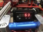
Already had the paint, parts, steel, welder, and a little bit of free time. Added the CHT sensor that is super accurate. Had my garage set to 72f working all day saturday, hooked up the CHT and it read 72. Sweet! Havent ran the wide band.

Both have 0-5v output so i can tie into my dyno software for datalogging. But first i want to see about getting some shielded wire, likely 18 gauge so i can tie it into my wiring harness for my computer.

I like the colors, did it with an airbrush with autoair colors, but did not clear coat. Kind of sort of matches the dyno when you look at it.
 

Attachments

  • IMG_4712.jpg
    IMG_4712.jpg
    404 KB · Views: 9
  • IMG_4713.jpg
    IMG_4713.jpg
    310.6 KB · Views: 7
  • IMG_4715.jpg
    IMG_4715.jpg
    244 KB · Views: 8
  • IMG_4716.jpg
    IMG_4716.jpg
    206.3 KB · Views: 7
  • IMG_4717.jpg
    IMG_4717.jpg
    295.5 KB · Views: 7
  • IMG_4718.jpg
    IMG_4718.jpg
    226 KB · Views: 7
  • IMG_4719.jpg
    IMG_4719.jpg
    319.7 KB · Views: 7

KartFab

Active member
Messages
3,381
Reaction score
55
Location
Dallas, TX
If this dyno works accurately and consistently, do you plan on bringing it with to the meet ups?

I have thought about it, but it is looking like I’ll have to refrain for now.

Performance trends, the people that make the software for inertia dynamometer, said that inertia dyno numbers are typically inflated by 20-30% in the karting scene. They also went on to say that I should just inflate my water brake numbers by that amount. I’m not all about that, at all. I’m put off by that. They also went on to say that a lot of “corrected hp” numbers only use standard correction instead of SAE correction (the gold standard for HP correction. Standard correction shows 3-4% higher numbers than SAE, so even “corrected” numbers can and are inflated compared to SAE.

My initial findings, which all sources are kept confidential, shows that my stage 4 predator makes 23.1% “more hp” on an inertia dyno.

My other findings show that a 6.5 hp predator 212 makes 6.5 hp on my brake dyno with SAE correction (accurate). My initial findings, which are not based on data (yet) show that there could be more variance in back to back runs on a water brake vs an inertia dyno.

So when you hear crazy high numbers people are making with their engines, just take 20-30% off of that and that will be a more realistic hp number (accurate). However, I believe they may be an exponential or some sort of non linear relationship between hp between brake/inertia Dynos as rpm increases (e.g 11% difference at 3600 rpm and 20-30% difference st 7500 rpm).

Engine manufacturers have been sued by inflating their numbers. Lost out on millions in court settlements because the engines they said made X hp st 3600, made a lot LESS. Now these manufacturers are required to state that their hp numbers are either net hp (ran with air filter and muffler) or gross hp (ran without muffler or air filter), and if they provide a correction factor, the SAE method must be followed (which just isn’t a correction factor, but a bible of procedures to follow).

So I don’t want to go out stating well your engine makes X hp yet, especially with this whole inflated hp numbers game going on. Lots of broken hearts and disbelief will go on. Just going to show all sides to this conundrum with data.
 
Status
Not open for further replies.
Top