How to connect/install a YK31 speed controller

Status
Not open for further replies.

Functional Artist

Well-known member
Messages
5,333
Reaction score
2,815
Location
Toledo, Ohio

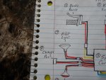
Here are the (10) main components that are needed to connect/install this YK31C speed controller

1.) Motor (24V 450W)
2.) Speed Controller (24V 500W)
3.) Battery Pack (2 - 12V/12AH SLA Batteries)
4.) Throttle (can be a twist throttle, thumb throttle or a pedal throttle)
5.) On/Off Switch (can be a simple toggle, rocker or a key switch)
6.) Brake Switch (usually a small switch mounted to the brake lever or pedal)
7.) Pilot Light (to power a head light or running lights)
8.) Charge Port (to connect an accessible plug to attach a battery charger)
9.) Brake Light (to power a rear light to indicate when you apply the brakes)
10.) Fuse & Holder (cheap insurance to protect your investment)

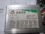
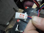
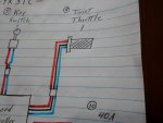
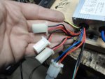
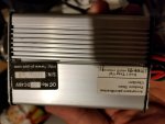
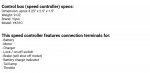
The speed controller, that we have, has "some" wiring instructions printed right on the label.
But, it only shows (6) plugs & the controller actually has (8) plugs
(some of the plugs are labeled but, not all of them)

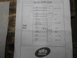
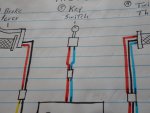
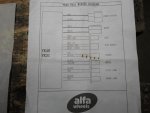
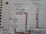
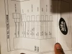
Luckily, our friends at Alfa Wheels sent printed wiring definitions
 

Attachments

  • SAM_8120.jpg
    SAM_8120.jpg
    233.8 KB · Views: 39
  • SAM_8125.jpg
    SAM_8125.jpg
    258.8 KB · Views: 38
  • SAM_8116.jpg
    SAM_8116.jpg
    204.9 KB · Views: 61
Functional Artist

Well-known member
Messages
5,333
Reaction score
2,815
Location
Toledo, Ohio
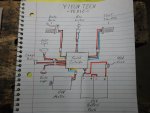
So, according to the diagram
...this is how the plugs are labeled
...& what they do

1.) Power -thick red (+), thick black (-)
...connects the battery pack to the speed controller
2.) Motor -thick blue (+), thick white (-)
...connects the motor to the speed controller
3.) Lock -thin blue, thin red (VCC)
...connects a switch to the speed controller, used for turning it on or off
4.) Throttle -thin red (5V), thin black (GND), thin blue (SIGNAL)
...connects a throttle to the speed controller, used for speed adjustment
5.) Charge - thin red (+), thin black (-)
...connects a charge port to the speed controller, used to attach a battery charger
6.) Brake -thin black, thin yellow
...connects a brake switch to the speed controller, when applied it cuts power to the motor & activates a brake light
7.) Pilot lamp -thin black, thin red
...connects a head light to the speed controller
8.) Brake Lamp -thin black, thin red
...connects a brake light to the speed controller, activated by the brake switch
 

Attachments

  • SAM_8115.jpg
    SAM_8115.jpg
    244.8 KB · Views: 91
Functional Artist

Well-known member
Messages
5,333
Reaction score
2,815
Location
Toledo, Ohio
Here is "how to" get everything connected, step by step :thumbsup:

According to the wire/plug definitions, #1 Power, is to connect the battery pack. We'll skip that for now.
It's actually the last thing that we need to connect.

Next is #2 Motor -connecting the motor to the speed controller
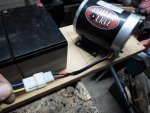
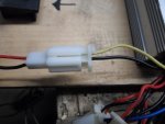
This should be the easiest connection to make (if you bought your motor & speed controller together)
because they should have mating plugs, one male & one female.

The weird thing is the wire colors don't match. (I guess its a Chinese thing?) :ack2:

The motor wires coming out of the speed controller are thick yellow & thick blue
(IDK why but, the definitions show the wires as blue & white?)
& the wires coming out of the motor are thick red & thick black

But, its OK because with many of these brushed motors you can connect them either way.
When connected one way (speed controller yellow to motor black & speed controller blue to motor red) the motor turns clockwise & when connected the other way (speed controller blue to motor black & speed controller yellow to motor red) the motor turns counterclockwise (goes the other way)

So, for this one you should be able to just plug them together :cheers2:

If the motor rotates the wrong way, when mounted on your kart, we can just switch a couple of wires :2guns:

We will cover "how to" switching wires shortly :cool:
 

Attachments

  • SAM_8149.jpg
    SAM_8149.jpg
    264.9 KB · Views: 10
  • SAM_8148.jpg
    SAM_8148.jpg
    173.3 KB · Views: 5
  • SAM_8146.jpg
    SAM_8146.jpg
    202.6 KB · Views: 11
  • SAM_8202.jpg
    SAM_8202.jpg
    264.7 KB · Views: 29

Functional Artist

Well-known member
Messages
5,333
Reaction score
2,815
Location
Toledo, Ohio
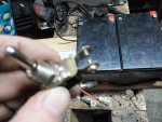
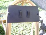
#3 Lock -connects a standard on/off switch to the speed controller
The switch is usually mounted up front, on the dash board, handle bar or steering wheel
The "kill switch", if your kart had one, can be reused here. :thumbsup:

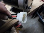
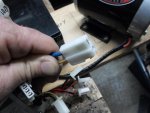
So, we need to run (2) wires from the dash area back to where the speed controller is mounted but, the Lock wires (thin blue & thin red) coming out of the speed controller have a male plug on the end of them.

What do you do if you don't have a matching female plug?

Well we have (3) main options

1.) Look online to find matching plugs (it's the most expensive option & a PITA)
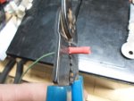
2.) cut the plug off, solder on some extension wires & heat shrink the connection
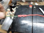
3.) cut the plug off & use some crimp ends to add the extension wires on.

Once the (2) extension wires are connected to the (2) Lock wires from the speed controller & run along the frame, up to the switch, in the front

Leaving a little slack, cut the extension wires off & then add the appropriate crimp ends to connect the wires to the switch. :2guns:
 

Attachments

  • SAM_8142.jpg
    SAM_8142.jpg
    268.7 KB · Views: 18
  • SAM_6681.jpg
    SAM_6681.jpg
    325.8 KB · Views: 14
  • SAM_8157.jpg
    SAM_8157.jpg
    196.3 KB · Views: 16
  • SAM_8159.jpg
    SAM_8159.jpg
    222.4 KB · Views: 16
  • SAM_8201.jpg
    SAM_8201.jpg
    272.4 KB · Views: 20
  • SAM_8204.jpg
    SAM_8204.jpg
    232.8 KB · Views: 19

Functional Artist

Well-known member
Messages
5,333
Reaction score
2,815
Location
Toledo, Ohio
Lets look at this a little closer before we move on :thumbsup:

Ok, so we cut the plug off & now we have (2) cut wire ends (1) red & (1) blue

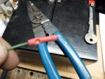
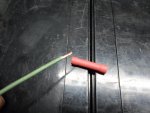
Whether we solder or use crimp ends, we have to first remove ~1/4" of the insulating cover off each of the wire ends.

The easy way (to crimp):
Simply slide the end of the bared (red) wire into a "butt-connector" & crimp it securely with a crimping tool.
Then slide the bared end of a piece of (red) extension wire into the other end & crimp securely.
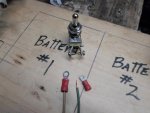
Up front, on the switch end, again bare ~1/4" of wire & then crimp on a spade (flat) or ring (round) terminal that will connect to your on/off switch
Then, cover all connections with heat shrink

Now,
The best way (to solder):
Tin (to coat with solder) the bared ends of each your wires
Solder extension wires to each of your "Lock" wires & cover with heat shrink
Up front, on the switch end either solder or crimp on the appropriate ends to connect to your on/off switch.
 

Attachments

  • SAM_8175.jpg
    SAM_8175.jpg
    259.8 KB · Views: 6
  • SAM_8177.jpg
    SAM_8177.jpg
    226.1 KB · Views: 1
  • SAM_8171.jpg
    SAM_8171.jpg
    243.5 KB · Views: 1
  • SAM_8170.jpg
    SAM_8170.jpg
    199.1 KB · Views: 2
  • SAM_8165.jpg
    SAM_8165.jpg
    250.7 KB · Views: 3
  • SAM_8193.jpg
    SAM_8193.jpg
    193.1 KB · Views: 4
  • SAM_8197.jpg
    SAM_8197.jpg
    266.9 KB · Views: 9
  • SAM_8198.jpg
    SAM_8198.jpg
    265.3 KB · Views: 10
  • SAM_8215.jpg
    SAM_8215.jpg
    197.8 KB · Views: 11
  • SAM_8212.jpg
    SAM_8212.jpg
    220.3 KB · Views: 6

Functional Artist

Well-known member
Messages
5,333
Reaction score
2,815
Location
Toledo, Ohio
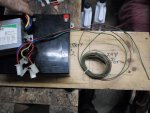
You need to have a plan (or at least a rough idea) for where you can fit everything in & mounted securely & that the wires will reach to for easy connecting.

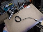
So, for this demonstration, I am just going to mount our main components to a board with some handle bars.

To give a rough layout of where everything goes :thumbsup:

See pic. below

Up front (left side of the board) is where you would have your controls
...on/off switch (mounted to the dash)
...throttle control (mounted on the right handle) (or right pedal)
...brake lever (mounted on the left handle) (or left pedal)

In the rear (right side of the board) is where you would have your propulsion components
...battery pack
...motor
...speed controller
 

Attachments

  • SAM_8123.jpg
    SAM_8123.jpg
    221.7 KB · Views: 7
  • SAM_8121.jpg
    SAM_8121.jpg
    247.2 KB · Views: 5

Functional Artist

Well-known member
Messages
5,333
Reaction score
2,815
Location
Toledo, Ohio
#4 Throttle - connects the throttle to the speed controller

This should be another of the easier connections because it's the only plug with (3) wires & the end plug on the throttle should mate up with the "throttle" end plug on the speed controller.

The main thing to watch for, here, is that the wire colors from one plug end match or align with the wire colors on the other plug.

It should be wired as:
...red wire to red wire (5V)
...black wire to black wire (GND)
...other color to other color (signal)
(I have seen many different colors used for the signal wire)

If they match up or align, that's great!

Plug them together
...be sure the retainer clip engages
...& move on :thumbsup:

* If not, no problem
... we'll just have to switch a couple of wires around :cheers2:
 

Attachments

  • SAM_8138.jpg
    SAM_8138.jpg
    243.6 KB · Views: 11
  • SAM_8117.jpg
    SAM_8117.jpg
    196.7 KB · Views: 14
  • SAM_8205.jpg
    SAM_8205.jpg
    246.1 KB · Views: 10
  • SAM_8249.jpg
    SAM_8249.jpg
    190.5 KB · Views: 13

Functional Artist

Well-known member
Messages
5,333
Reaction score
2,815
Location
Toledo, Ohio
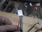
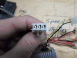
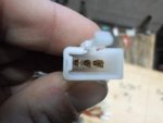
Switching the wires around on these speed controllers, motors & throttles is no big deal
...once you understand the concept of how they work :cool:

We'll start with the bigger (motor) size plug first (easier to see what's what)

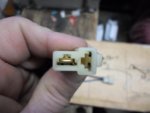
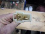
There is a female plug (first & second pic) & a male plug (third pic)

You can unlatch, remove & switch the wires in either plug
but, I have found that it is usually easier to switch the wires in the female plug

You can use a paper clip but, they bend kinda easy
I have had better success using a very small Allen wrench :thumbsup:

Looking into the Female plug,
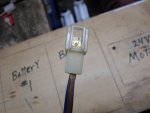
...you can see the (2) male spade terminals
...inside the bottom, next to each spade is a small recess
...you have to insert the wire or wrench into the recess
...push in toward the spade, with the tool & downward
...this should release the retainer clip (little catch) on the side of the spade
...gently pull on the wire from the other end
...& it should slide right out

Repeat the procedure for the other wire

Before reinserting the proper wire, into the proper slot
...use a small pocket knife blade
...to make sure the retainer clip on the side of the spade
...sticks out far enough to catch in the recess, when it's reinserted :cheers2:
 

Attachments

  • SAM_8235.jpg
    SAM_8235.jpg
    163.5 KB · Views: 1
  • SAM_8236.jpg
    SAM_8236.jpg
    159.5 KB · Views: 0
  • SAM_8237.jpg
    SAM_8237.jpg
    176.4 KB · Views: 1
  • SAM_8238.jpg
    SAM_8238.jpg
    197 KB · Views: 3
  • SAM_8239.jpg
    SAM_8239.jpg
    179.8 KB · Views: 2
  • SAM_8240.jpg
    SAM_8240.jpg
    174.8 KB · Views: 2
  • SAM_8241.jpg
    SAM_8241.jpg
    156.8 KB · Views: 0
  • SAM_8242.jpg
    SAM_8242.jpg
    149 KB · Views: 1
  • SAM_8251.jpg
    SAM_8251.jpg
    216.4 KB · Views: 2

Functional Artist

Well-known member
Messages
5,333
Reaction score
2,815
Location
Toledo, Ohio
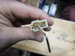
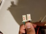
The small plugs work the exact same way as the bigger ones :thumbsup:
...everything is just a bit smaller

First (2) pics are of small female plugs
The third pic is of a small male plug

This is where you may need to use a tool with a smaller shaft, like a paperclip
...to fit into the smaller recess

It's the same concept as before
...stick the tool into the recess
...push toward the spade terminal
...while pushing downward
...& gently pull the wire out of the slot

Be sure the retainer clip is sticking out enough, to catch in the recess, when the spade is reinserted :cheers2:
 

Attachments

  • SAM_8229.jpg
    SAM_8229.jpg
    206.5 KB · Views: 2
  • SAM_8231.jpg
    SAM_8231.jpg
    180.3 KB · Views: 2
  • SAM_8234.jpg
    SAM_8234.jpg
    168.5 KB · Views: 1
  • SAM_8233.jpg
    SAM_8233.jpg
    180.6 KB · Views: 1

Functional Artist

Well-known member
Messages
5,333
Reaction score
2,815
Location
Toledo, Ohio
Quick review :thumbsup:

Wiring diagram
1.) Power -thick red (+), thick black (-)
...connects the battery pack to the speed controller
2.) Motor -thick blue (+), thick white (-)
...connects the motor to the speed controller
3.) Lock -thin blue, thin red (VCC)
...connects a switch to the speed controller, used for turning it on or off
4.) Throttle -thin red (5V), thin black (GND), thin blue (SIGNAL)
...connects a throttle to the speed controller, used for speed adjustment
5.) Charge - thin red (+), thin black (-)
...connects a charge port to the speed controller, used to attach a battery charger
6.) Brake -thin black, thin yellow
...connects a brake switch to the speed controller, when applied it cuts power to the motor & activates a brake light
7.) Pilot lamp -thin black, thin red
...connects a head light to the speed controller
8.) Brake Lamp -thin black, thin red
...connects a brake light to the speed controller, activated by the brake switch

Now that the motor, the lock (on/off switch) & the throttle are all connected
& if, we connected the battery pack, the motor would function

These are referred to as the "mandatory" connections

But, what about the other plugs? (#5,6,7 & 8)

Those are referred as "optional" connections
We are going to cover those next

* IMHO, for safety, #6 brake, should have been a mandatory connection also, because it cuts power to the motor when the brakes are applied
So the motor cannot go while your trying to stop :cheers2:

Lets get the brake switch connected, it's another one of the easier connection to make

The brake switch circuit is what is called an open circuit meaning that when the brakes are applied the switch closes the circuit
...turning the power to the motor off
...& sending 12V to the brake light, thru the brake lamp plug

We have (4) plugs left to connect, according to the diagram the brake plug has thin black & yellow wires

(the other (3) plugs, the charge port, pilot lamp & brake lamp all have thin red & black wires)

WOW! who's bright idea was that? :ack2:

If the lever or brake switch that your are using has a matching plug, simply plug them together

If not, just cut the plug end off & connect each wire (using previously prescribed methods) to extension wires, that connect to each side of your switch (so when you activate the switch it closes the circuit) :2guns:
 

Attachments

  • SAM_8134.jpg
    SAM_8134.jpg
    228 KB · Views: 2
  • SAM_8208.jpg
    SAM_8208.jpg
    263 KB · Views: 11
  • SAM_8264.jpg
    SAM_8264.jpg
    232.4 KB · Views: 1
  • SAM_8260.jpg
    SAM_8260.jpg
    184.9 KB · Views: 2

Functional Artist

Well-known member
Messages
5,333
Reaction score
2,815
Location
Toledo, Ohio
Now for the last (3) plugs
Remember, they all (3) have thin red & black wires
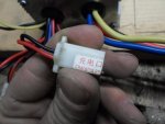
The brake lamp & charge plug, both have labels on them.
The pilot lamp plug did not the label must have fallen off.

To be sure, I double checked each of them (with the battery pack connected) with my multi meter

The charge port plug showed 25.9V (full pack voltage)
The pilot lamp plug showed 25.9V (full pack voltage)
& the brake lamp plug did not show any voltage reading
But, when the brake lever was activated, the brake lamp plug also showed 25.9V (full pack voltage) :cheers2:

* I figured that the speed controller would reduce the voltage out put to 12V so standard light bulbs could be used for the pilot light & the brake light

** So, I guess a voltage divider would need to be rigged up or a voltage reducer like used on golf carts could be used to connect 12V pilot & brake lights
 

Attachments

  • SAM_8267.jpg
    SAM_8267.jpg
    215.7 KB · Views: 5
  • SAM_8268.jpg
    SAM_8268.jpg
    168.1 KB · Views: 3
  • SAM_8273.jpg
    SAM_8273.jpg
    198 KB · Views: 4
  • SAM_8307.jpg
    SAM_8307.jpg
    290.3 KB · Views: 7

ian928

Member
Messages
32
Reaction score
2
Location
Norway
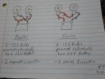
Could you not connect the pilot and brake lights in series? That is my plan for my 4YO’s 24V controller.
 

Functional Artist

Well-known member
Messages
5,333
Reaction score
2,815
Location
Toledo, Ohio
Could you not connect the pilot and brake lights in series? That is my plan for my 4YO’s 24V controller.

Yup!, connecting (2) 12V lights in series, should work with this 24V system :thumbsup:

Ima gonna give it a try :cheers2:

Remember, the pilot & brake lights are (2) different circuits
...the pilot light circuit is "live" when the speed controller is turned on
...but, the brake light circuit is not "live" until the brake lever is activated

So, I think we need to use (2) lights, wired in series, for each circuit
...(2) 12V bulbs for the pilot light
...& (2) 12V bulbs for the brake light :2guns:
 

Functional Artist

Well-known member
Messages
5,333
Reaction score
2,815
Location
Toledo, Ohio
Now, just gotta connect some extension wires for
...the running lights (up to the front) red to (+) black to (-) connected to (2-12V bulbs in series)
...the brake lights (back to the back) red to (+) black to (-) connected to (2-12V bulbs in series)
...& a charge port (for connecting a battery charger)

Once ALL connections are secure we can connect the battery pack :thumbsup:
Connect the thick black (-) wire to the battery pack negative (-) aka (GND)
Connect the thick red (+) wire to a fuse holder (with a 40A fuse) & then to the battery pack positive (+)

Yup, using (2) 12V light bulbs series works great!
Thanks again, to ian928
"Keeping it simple", I love it :thumbsup:

https://www.youtube.com/watch?v=2GlF2aqdXQ4
 

Attachments

  • SAM_8209.jpg
    SAM_8209.jpg
    257.8 KB · Views: 4
  • SAM_8346.jpg
    SAM_8346.jpg
    228.4 KB · Views: 3
  • SAM_8342.jpg
    SAM_8342.jpg
    219.8 KB · Views: 3
  • SAM_8359.jpg
    SAM_8359.jpg
    225.8 KB · Views: 6
  • SAM_8356.jpg
    SAM_8356.jpg
    238.3 KB · Views: 7

ian928

Member
Messages
32
Reaction score
2
Location
Norway
Yup!, connecting (2) 12V lights in series, should work with this 24V system :thumbsup:

Ima gonna give it a try :cheers2:

Remember, the pilot & brake lights are (2) different circuits
...the pilot light circuit is "live" when the speed controller is turned on
...but, the brake light circuit is not "live" until the brake lever is activated

So, I think we need to use (2) lights, wired in series, for each circuit
...(2) 12V bulbs for the pilot light
...& (2) 12V bulbs for the brake light :2guns:

Ahhh, Its a bike! Didnt realise that... My sons car has two pilot lights and two brake lights anyway. Maybe you can find 24V bulbs you could use instead?
 

Functional Artist

Well-known member
Messages
5,333
Reaction score
2,815
Location
Toledo, Ohio
Do you have any idea what this plug is? It is labeled "Sport"

View attachment 96011

View attachment 96012

Thanks!

I have not seen a "sport" plug before
But, if I was to guess
I would say like maybe for a "high speed" switch (sport mode) :thumbsup:

What controller do you have & where did you get it?
...maybe we can find more "specific" info on it :2guns:

---------- Post added at 06:29 PM ---------- Previous post was at 06:24 PM ----------

Ahhh, Its a bike! Didnt realise that... My sons car has two pilot lights and two brake lights anyway. Maybe you can find 24V bulbs you could use instead?

Nah, I like the simplicity of using "standard" 12V bulbs :thumbsup:

I'll just use (2) for 24V, (3) for 36V & (4) for 48V :2guns:

Thanks again, for the simply, brilliant idea :cheers2:
 

mcrcat

New member
Messages
8
Reaction score
0
I am also curious about the output of the plug labeled "indicator." In the description I showed in the photo above it says "battery charge indicator" but I have no idea what type of signal it puts out and what to hook up to it.

---------- Post added at 09:24 PM ---------- Previous post was at 08:52 PM ----------

One more update. I went ahead and shorted the two wires in the "sport" plug while holding full throttle and noticed no power difference with the wires shorted closed or open. Now I am even more curious what it does! One thing to note however I was running 4 12v SLA batteries in series for 48v but they are brand new and haven't been charged by me yet. So I am not sure how many volts they were actually producing. Maybe they are lower already and that's why shorting the wires to maybe a low "sport" setting produced no change vs regular unshorted "sport" mode. I am just thinking out loud here.
 

alfa-wheels

New member
Messages
5
Reaction score
0
Location
Hallandale Beach, FL
I have not seen a "sport" plug before
But, if I was to guess
I would say like maybe for a "high speed" switch (sport mode) :thumbsup:

What controller do you have & where did you get it?
...maybe we can find more "specific" info on it :2guns:

---------- Post added at 06:29 PM ---------- Previous post was at 06:24 PM ----------


Nah, I like the simplicity of using "standard" 12V bulbs :thumbsup:

I'll just use (2) for 24V, (3) for 36V & (4) for 48V :2guns:

Thanks again, for the simply, brilliant idea :cheers2:
Sport is normally for selecting speed (e.g. low, high). Just add a switch and test it.
Normally it is only provided with brush-less controllers only.
did you get one with reverse?

---------- Post added at 07:52 PM ---------- Previous post was at 07:50 PM ----------

I am also curious about the output of the plug labeled "indicator." In the description I showed in the photo above it says "battery charge indicator" but I have no idea what type of signal it puts out and what to hook up to it.

---------- Post added at 09:24 PM ---------- Previous post was at 08:52 PM ----------

One more update. I went ahead and shorted the two wires in the "sport" plug while holding full throttle and noticed no power difference with the wires shorted closed or open. Now I am even more curious what it does! One thing to note however I was running 4 12v SLA batteries in series for 48v but they are brand new and haven't been charged by me yet. So I am not sure how many volts they were actually producing. Maybe they are lower already and that's why shorting the wires to maybe a low "sport" setting produced no change vs regular unshorted "sport" mode. I am just thinking out loud here.
Indicator is a direct connection to the batteries, for voltage indication.
some throttles come with voltage reading via LCD screen or LED bar,
if you have any of these, (or any other voltage meter) just connect to these to get reading on battery charge.
 
Status
Not open for further replies.
Top