Functional Artist
Well-known member
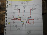
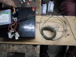
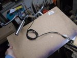
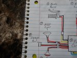
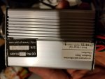
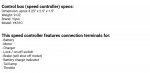
Here are the (10) main components that are needed to connect/install this YK31C speed controller
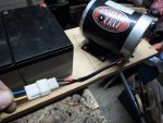
1.) Motor (24V 450W)
2.) Speed Controller (24V 500W)
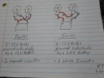
3.) Battery Pack (2 - 12V/12AH SLA Batteries)
4.) Throttle (can be a twist throttle, thumb throttle or a pedal throttle)
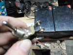
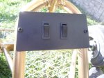
5.) On/Off Switch (can be a simple toggle, rocker or a key switch)
6.) Brake Switch (usually a small switch mounted to the brake lever or pedal)
7.) Pilot Light (to power a head light or running lights)
8.) Charge Port (to connect an accessible plug to attach a battery charger)
9.) Brake Light (to power a rear light to indicate when you apply the brakes)
10.) Fuse & Holder (cheap insurance to protect your investment)
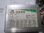
The speed controller, that we have, has "some" wiring instructions printed right on the label.
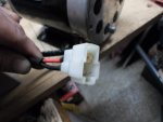
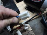
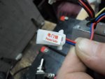
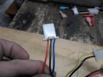
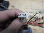
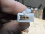
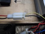
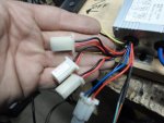
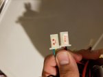
But, it only shows (6) plugs & the controller actually has (8) plugs
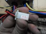
(some of the plugs are labeled but, not all of them)
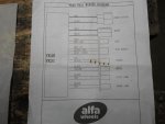
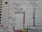
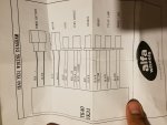
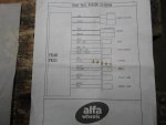
Luckily, our friends at Alfa Wheels sent printed wiring definitions
Attachments
-
 SAM_8120.jpg233.8 KB · Views: 39
 -
 SAM_8125.jpg258.8 KB · Views: 38
 -
 SAM_8116.jpg204.9 KB · Views: 61