Hemi Predator Build #2

Status
Not open for further replies.

Whitetrashrocker

Inmate #952016
Messages
4,799
Reaction score
3,993
Location
Southern New Mexico
Hey Bob! Can you weld? I don't keep track of everyone's garage...

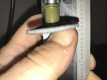
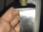
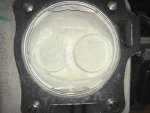
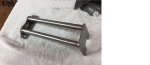
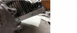
Take a c clamp thats big enough to go around the head. Cut the solid foot off the clamp and weld on a ring.

Use the clamp to compress the spring and the keepers can be removed or installed inside the ring.

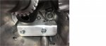
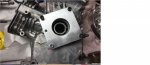
Made one to do the heads on the alky motor and it's a Time saver.

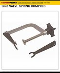
Kinda a ripoff of the camover style you find on the market. They use a cameltoe looking foot. We just put a ring. Much more stable and secure. We're using like 150lb springs though lol.
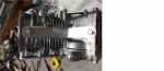
 

Attachments

  • IMG_20170724_144222.jpg
    IMG_20170724_144222.jpg
    149.4 KB · Views: 0

bob58o

SuckSqueezeBangBlow
Messages
9,646
Reaction score
1,850
Location
Chicago-town USA
To say I can weld might be a stretch. LOL
I own a welder and I have made noise and light. LOL
Sometimes I can get a decent weld.

I saw this video a year or two ago I think.
5:30 talks about his tool. Same as yours.
Uses a 4" Harbor Freight "C" clamp and what he calls a 1/2" nipple.
https://www.youtube.com/watch?v=13NssmZJi00

---------- Post added at 04:05 PM ---------- Previous post was at 03:53 PM ----------

They came out pretty easy with the tool I got.
Head held sideways. One hand holding the valve face. One hand compressing the spring with the tool. Compress and shake the keepers out.
 

Whitetrashrocker

Inmate #952016
Messages
4,799
Reaction score
3,993
Location
Southern New Mexico
Now using both hands to hold the head and compress the spring, put the keepers back on. Lol.


The video shows exactly what we did. Kinda. Different design but same concept.
 

bob58o

SuckSqueezeBangBlow
Messages
9,646
Reaction score
1,850
Location
Chicago-town USA
Now using both hands to hold the head and compress the spring, put the keepers back on. Lol.


The video shows exactly what we did. Kinda. Different design but same concept.

I'm not too proud to say I was just holding a telescoping magnet in my mouth.

On the flip side, I'm going to try a rolled up sock in the chamber with the gasket surface on the table. One hand on the tool, one positioning the keepers. We shall see if I can do it. And the number of hours and F bombs I drop while attempting.

---------- Post added at 04:26 PM ---------- Previous post was at 04:20 PM ----------

Ok, so my last issue is that the dremel ez attachment thing has some play in it. So that when I lower the drill press on the piston, the grinding wheel tilts. This changes the angle. So If I was coming in at 12 degrees, and the wheel tilts 5 degrees, now I'm coming in at 7 degrees. I suppose I can just adjust for it. If the tilt is 5 degrees, I can set the table at 17 instead of 12.
Unless there are better options??
 

Whitetrashrocker

Inmate #952016
Messages
4,799
Reaction score
3,993
Location
Southern New Mexico
A real mill with a fly bit. Duhh.

---------- Post added at 03:33 PM ---------- Previous post was at 03:31 PM ----------

Ok enough SA.
Pics please?
Why a dremel attachment on the drill press. Use the Chuck provided with one tool.
 

bob58o

SuckSqueezeBangBlow
Messages
9,646
Reaction score
1,850
Location
Chicago-town USA
This is the only grinding wheel close to the size I want.
It was 1 1/2" now I made it 1 1/4".

It has this ez lock style connector for the ez lock mandrel.

A washer or two might do the trick to take up the play from the spring in the mandrel??
 

Attachments

  • IMG_1054.jpg
    IMG_1054.jpg
    163 KB · Views: 1
  • IMG_1053.jpg
    IMG_1053.jpg
    187.6 KB · Views: 1
  • IMG_1055.jpg
    IMG_1055.jpg
    112.2 KB · Views: 1
  • IMG_1051.jpg
    IMG_1051.jpg
    205.6 KB · Views: 1
  • IMG_1050.jpg
    IMG_1050.jpg
    237.7 KB · Views: 1

Whitetrashrocker

Inmate #952016
Messages
4,799
Reaction score
3,993
Location
Southern New Mexico
I wouldn't do that. Real mill tools are sturdy for a reason. You need to hold tight tolerances.
For what your doing you can Jerry rig a little. That's a little too much. Imo.

---------- Post added at 03:59 PM ---------- Previous post was at 03:58 PM ----------

Can you sourse something like that in a solid arbor?
 

bob58o

SuckSqueezeBangBlow
Messages
9,646
Reaction score
1,850
Location
Chicago-town USA
This nut places around the Mandel seems to reduce the tilt from 5 degrees to 1 degree.

As measured by the compass/level on the iPhone.
It surprisingly measured 12 degrees when I tilted the table 12 degrees based on the markings on the drill press.
 

Attachments

  • image.jpg
    image.jpg
    170.9 KB · Views: 2
  • IMG_1056.PNG
    IMG_1056.PNG
    42.2 KB · Views: 0

bob58o

SuckSqueezeBangBlow
Messages
9,646
Reaction score
1,850
Location
Chicago-town USA
So far I'm happy. I guess I need to see if it is in the right spot.

I already lost a keeper!:furious2:
 

Attachments

  • IMG_1063.jpg
    IMG_1063.jpg
    148.7 KB · Views: 8
  • IMG_1061.jpg
    IMG_1061.jpg
    459.3 KB · Views: 5
  • IMG_1058.jpg
    IMG_1058.jpg
    235.8 KB · Views: 8
  • IMG_1057.jpg
    IMG_1057.jpg
    194.5 KB · Views: 9
  • IMG_1068.jpg
    IMG_1068.jpg
    397.6 KB · Views: 10
  • valve location.jpg
    valve location.jpg
    404.1 KB · Views: 3

bob58o

SuckSqueezeBangBlow
Messages
9,646
Reaction score
1,850
Location
Chicago-town USA
How did you get that bit so fast?

LOL I read 543 and 801 and then went to Home Depot. 2 1/2 miles from my place.
They had 543, not 801.

543 might have cut enough, but I wanted to go deeper. The screw on the end prevented me from going to 0.065" like I wanted to. I went as deep as I could with a 0.003" feeler gauge tween the screw and the piston.

The grinding wheel (when flipped over - label side towards the piston) allows you to cut deeper. The wheel has a dome/cup in the center which keeps the end of the mandrel away from the piston for flush grinding. The nut I tossed on between the chuck and the mandrel head kept the ez lock mandrel pretty rigid in the chuck.
 

mckutzy

Well-known member
Messages
8,353
Reaction score
108
Location
bc, canada
I am loosely following this thread, as im interested in the experimentation's. However I have to ask... Why choose this route to "freehand" the valve notch via the drillpress, than the previous method described of using the valve as a cutter in the head for alignment/positioning?

https://www.youtube.com/watch?v=Jpk2pKASjBE
 

bob58o

SuckSqueezeBangBlow
Messages
9,646
Reaction score
1,850
Location
Chicago-town USA
I would of had to order a 32mm SS valve, grind it to like 31mm, cut the teeth to make it a cutter, buy a drill extension, and hope for the best.

I agree, It would have been the better option. Takes most of the guess work out of it. Only costs like $25 - $30.

---------- Post added at 11:19 PM ---------- Previous post was at 10:37 PM ----------

I figured I needed to cut the relief 0.038" deep minimum. I was at like 0.030" piston to valve clearance. I still needed to account for the smaller gasket (-0.018") and wanted at least 0.050" clearance. So 0.050 - 0.030 + 0.018 = 0.038".

It measured 0.063" deep at the edge of the relief. This was planned. Not cause I like to throw compression in the trash. The relief is bigger than the valve. You need to make the relief have a diameter 0.100" bigger than that of the valve.

So due to the 12 degree angle, if I needed ~0.040" with 28.5mm, I need deeper with 31.75mm (size of the cutter).

Where the valve should come closest, the relief is 0.040 - 0.050" deep. Somewhere in that range.

Should have around 0.060" Intake Valve Clearance and like 0.065" radial clearance. Lets see if I can install this 37lb spring and check.
 

bob58o

SuckSqueezeBangBlow
Messages
9,646
Reaction score
1,850
Location
Chicago-town USA
Got the intake valve installed with the 37lb spring! Almost two hours and a bunch of frustration. And since I lost a keeper already, I can't install the exhaust valve. I think I have a spare, but can't find the bag - o - parts I think it is in.

Anyway. I'll install the cam, dab the piston valve relief area with clay, put the head on / install the pushrods, tighten the head bolts, make sure the lifters are on the cam base circle (TDC compression stroke), set for zero valve lash and see how we did.

---------- Post added at 02:03 AM ---------- Previous post was at 01:16 AM ----------

I tested with clay. The valve impression was pretty centered in the valve relief. I measured 0.070" at the closest point. Any way. I'm happy and satisfied with this!!!!! Its probably close to 0.2cc if I had to guess.

EDIT: I guess I should put the side cover on and test again.
:oops:
 

Noseoil

Terrible Tim
Messages
57
Reaction score
5
Location
Tucson
You can make a "cast" of the relief cut with clay & then peel it out. Roll it into a pellet & drop it into a graduated cylinder with water in it. Then you can read what the volume is if you need to know the exact amount of additional chamber cc you have from the cuts into the piston.
 

bob58o

SuckSqueezeBangBlow
Messages
9,646
Reaction score
1,850
Location
Chicago-town USA
You can make a "cast" of the relief cut with clay & then peel it out. Roll it into a pellet & drop it into a graduated cylinder with water in it. Then you can read what the volume is if you need to know the exact amount of additional chamber cc you have from the cuts into the piston.

Can I borrow your graduated cyclinder? Just kidding. My tool for CC'ing needs an upgrade. I did this already, but trying to eyeball 0.125 - 0.200 CC on a $2 tool with only markings every full CC isn't very accurate.

---------- Post added at 08:54 AM ---------- Previous post was at 08:48 AM ----------

BTW a little tid bit of info I figured out....
When the timing marks on the crank and the camshaft align, the piston should be around TDC on the Compression Stroke. So If the side cover is off, you can use this to make sure the lifters are sitting on the cam's base circle for setting valve lash.
Not sure if everybody knew that already. I did not.
 

bob58o

SuckSqueezeBangBlow
Messages
9,646
Reaction score
1,850
Location
Chicago-town USA
Thanks to David Wulf for these awesome pictures.
And to BlocDoc for sharing this text....

This is some of the coolest stuff I've seen in a while.
Engine is not so stock appearing any more. It's scary looking. Like a Terminator / Predator.


"
Next buy or make a top plate that goes where your tank was.
You could even cut up a tank in a pinch.
This helps brace things.
Under the flywheel where the lighting coils go make a brace that ties all 4 bolts together there too.
Case cover side tie all four holes together and make a plate that extends all the way to head.
tray and catch every bolt on the way to tin work for the cooling shroud.
make a plate that braces the low oil shut off inside the case ( even better if its a piece of angled aluminum that closes off the area and leaves a void where oil is not violently whipped around, this is not a windage tray its just a quiet place in the block where oil is not whipped into foam ).
Make a triangular plate that connects the ears for the fuel tank to the oil plug at the bottom of the block.

All these little braces make the block stiffer and reduce the flex( flex is what causes the bolts to loosen )

The blocks are not very strong and were not designed for this.
But you can make then stronger just buy adding some simple braces and above all good bolts tightened to 17 foot pounds.

Yes you can make a brace its easy.
Just find some 3/16 cold roll aluminum plate ( very common )
Cut drill and bolt on everywhere you see bolt holes not used on the block to tie things together.

I won't upload anything here anymore, but if your still stuck on this send me a PM and I will emmail you some pictures of easy bracing"
 

Attachments

  • bb4.jpg
    bb4.jpg
    164.1 KB · Views: 7
  • bb3.jpg
    bb3.jpg
    99.8 KB · Views: 9
  • bb2.jpg
    bb2.jpg
    119.2 KB · Views: 8
  • bb1.jpg
    bb1.jpg
    144.5 KB · Views: 10
  • bb5.jpg
    bb5.jpg
    133.1 KB · Views: 8
  • bb6.jpg
    bb6.jpg
    99.9 KB · Views: 9
  • bb7.jpg
    bb7.jpg
    121.9 KB · Views: 8
  • bb8.jpg
    bb8.jpg
    163.4 KB · Views: 9
Status
Not open for further replies.
Top