bob58o
SuckSqueezeBangBlow
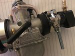
I think it looks awesome.
I'll have to wait to see how it looks on the bike.
I think it looks like my carb just docked with the International Space Station and a Russian Cosmonaut named Boris is banging on things with a pipe wrench inside the crank case.
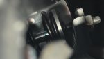
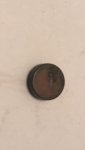
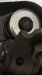
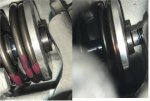
I like the idea of the carb pointed back with the 45 degree hose, but not as much as the 135 degree so it would point towards the front. I would cut it as short as possible. It would probably still be in the way of my leg and make the least power, but it would look cool and I could call it a ram air intake. Possibly use a screen like this? To shorten the overall length. Maybe with some nylon for added filtration?
Attachments
-
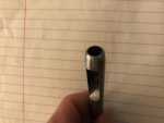
 135.jpg228 KB · Views: 5
 -
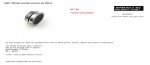 filter.jpg78.6 KB · Views: 7