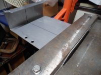
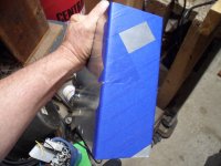
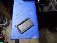
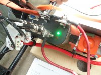
When we were discussing the Voltage indicator, there were a couple of technical terms (for real this time)
...so, let's take a look at the FSAE Rules for 2022 (again)
 EV - ELECTRIC VEHICLES
EV.1 DEFINITIONS
EV - ELECTRIC VEHICLES
EV.1 DEFINITIONS
EV.1.1 Tractive System – TS Every part electrically connected to the Motor(s) and/or Accumulator(s)
* The Tractive System is the entire electrical "drive line"
EV.1.2 Grounded Low Voltage - GLV Every electrical part that is not part of the Tractive System
* The GLV is all other electrical components (like meters & DC to DC convertors)
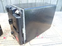
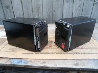
EV.1.3 Accumulator All the battery cells or super capacitors that store the electrical energy to be used by the Tractive System
* The Accumulator is the Battery pack
EV.3.2 Maintenance
EV.3.2.1 Safety glasses with side shields must be worn by all participating team members any time when:
a. Parts of the Tractive System are exposed while energized
b. Work is performed on the Accumulators
EV.3.2.2 Appropriate insulated tools must be used when working on the Accumulator or Tractive System
EV.4 ELECTRICAL LIMITATIONS
EV.4.1 Power and Voltage
EV.4.1.4 Supplying power to the motor to drive the vehicle in reverse is prohibited.
* Hmmm, no reverse is allowed
EV.4.2 Energy Meter
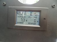
EV.4.2.1 All Electric Vehicles must run with the Energy Meter
* Yup, were gonna have an Energy Meter
 EV.5.2 Motor Controller The Tractive System Motor(s) must be connected to the Accumulator through a Motor Controller. No direct connections between Motor(s) and Accumulator.
* Yup, were gonna use a Kelly Controller
 EV.5.3.7 Each Accumulator Container must be labeled with the:
a. Symbol specified in ISO 7010-W012 (triangle with black lightning bolt on yellow background) with triangle side length of 100 mm minimum
EV.5.3.7 Each Accumulator Container must be labeled with the:
a. Symbol specified in ISO 7010-W012 (triangle with black lightning bolt on yellow background) with triangle side length of 100 mm minimum
b. Text “Always Energized”
c. Text “High Voltage” if the voltage meets T.9.1.1
* Ima gonna have ta get some of these stickers
EV.5.4 Grounded Low Voltage System
EV.5.4.1 The GLV System must be a Low Voltage system that is Grounded to the Chassis
EV.5.4.2 The GLV System must include a Master Switch, see EV.8.9.1
* The GLV System would be a low voltage system like a 12V circuit for lights & such
EV.5.9 Housings and Enclosures
EV.5.9.1 Every housing or enclosure containing parts of the Tractive System other than Motor housings, must be labeled with the:
a. Symbol specified in ISO 7010-W012 (triangle with black lightning bolt on yellow background)
b. Text “High Voltage” if the voltage meets T.9.1.1 EV.5.9.2 If the housing material is electrically conductive or possibly electrically conductive, it must have a low resistance connection to GLV System Ground, see EV.7.7
* Remember, were not actually going to have "High Voltage" since were only working with a 48V system
EV.6.2 Electrical Configuration
EV.6.2.1 All Tractive System components must be rated for the maximum Tractive System voltage
* This specifies that all wiring, switches & components "must" be rated for the maximum voltage that the system should ever have to "carry"
EV.6.2.4 Soldering electrical connections in the high current path is prohibited. Soldering wires to cells for the voltage monitoring input of the AMS is allowed, these wires are not part of the high current path.
* This specifies that all connections in the "high current" path "must" be "mechanical" connections & not soldered
** I'd say that's because soldered connections can "come loose" if the circuit becomes too hot
EV.6.4 Accumulator Isolation Relays - AIR
* AIR is a (technical term) for a contactor
** A contactor is a big "beefy" switch that contacts &/or isolates the Accumulator/Battery Pack from the Tractive System
...& is actuated/controlled by a smaller "signal" switch
EV.6.4.1 Every Accumulator Container must contain minimum one fuse (EV.7.6) and two or more Accumulator Isolation Relays (AIR)
EV.6.4.2 The Accumulator Isolation Relays must:
a. Be a Normally Open type
EV.6.5 High Voltage Disconnect - HVD A High Voltage Disconnect (HVD) must be included to quickly disconnect one or both poles of the Accumulator
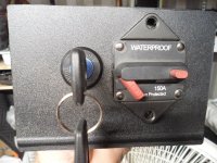
* Were using a 48V 150A circuit breaker as our HVD
EV.6.6 Precharge and Discharge Circuits
EV.6.6.1 The Accumulator must contain a Precharge Circuit. The Precharge Circuit must:
a. Be able to charge the Intermediate Circuit to minimum 90% of the Accumulator voltage before closing the second AIR
* Yup, were gonna have a pre-charge circuit to protect the capacitators in the controller from a huge "inrush" of current upon start-up
EV.6.6.3 The Tractive System must contain a Discharge Circuit. The Discharge Circuit must be:
a. Wired in a way that it is always active when the Shutdown Circuit is open
b. Able to discharge the Intermediate Circuit capacitors if the HVD has been opened
c. Not be fused
d. Designed to handle the maximum discharge current for minimum 15 seconds
* We don't (currently) have a discharge circuit
...but, IMO it's something we should probably to look into
EV.6.9 Tractive System Active Light - TSAL
EV.6.9.1 The vehicle must include a Tractive Systems Active Light (TSAL) that must:
a. Illuminate when the GLV System is energized to indicate the status of the Tractive System
* The TSAL (when lit) is to indicate that the System is "live"
EV.8.3 Accumulator Management System - AMS
EV.8.3.1 An Accumulator Management System must monitor the Accumulator(s) Voltage
* The AMS is another (technical term) for a BMS (Battery Management System)
EV.8.10 Shutdown Buttons
EV.8.10.1 Three Shutdown Buttons must be installed on the vehicle.
EV.8.10.2 Each Shutdown Button must be a push-pull or push-rotate emergency switch
EV.8.10.3 One Shutdown Button must be on each side of the vehicle which:
a. Is located behind the driver’s compartment at approximately the level of the driver’s head
b. Has a diameter of 40 mm minimum
c. Must not be easily removable or mounted onto removable body work
EV.8.10.4 One Shutdown Button must be mounted in the cockpit which:
a. Is located in easy reach of the belted in driver, adjacent to the steering wheel, and unobstructed by the steering wheel or any other part of the vehicle
b. Has diameter of 24 mm minimum
EV.8.10.5 The international electrical symbol (a red spark on a white edged blue triangle) must be near each Shutdown Button.
EV.8.10.6 Pressing any of the Shutdown Buttons must Open the Shutdown Circuit EV.8.2.2
* IMO having multiple Shut Down Buttons is redundant
...& are mainly for safety personnel during competition/track use.
EV.10.4.2 Tractive System Active
a. Definition – High Voltage is present outside of the Accumulator Container
b. Tractive System Active must not be possible until both: • GLV System is Energized • Shutdown Circuit is Closed
EV.10.4.3 Ready to Drive
a. Definition – the Motor(s) will respond to the input of the APPS
b. Ready to Drive must not be possible until:
• Tractive System Active • The brake pedal is pressed and held to engage the mechanical brakes T.3.1
• The driver performs a manual action to initiate Ready to Drive Such as pressing a specific button in the cockpit
EV.10.5 Ready to Drive Sound
EV.10.5.1 The vehicle must make a characteristic sound when it is Ready to Drive
EV.10.5.2 The Ready to Drive Sound must be:
a. Sounded continuously for minimum 1 second and a maximum of 3 seconds
b. A minimum sound level of 80 dBA, fast weighting IN.4.6
c. Easily recognizable. No animal voices, song parts or sounds that could be interpreted as offensive will be accepted
EV.10.5.3 The vehicle must not make other sounds similar to the Ready to Drive Sound.
* The RTDS is an audible sound that is emitted by the kart, when everything is "operating within specified parameters"
...& it is "Ready to Drive"