Go Kart Trailer... FINALLY!

Status
Not open for further replies.

OzFab

New member
Messages
15,615
Reaction score
8
Location
Warwick Qld, Australia
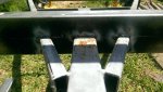
When I purchased a shifter kart rolling chassis a little over a year ago, I realised it wouldn't fit in my 7'x4' box trailer &, my AusEx had less chance because it was even wider so, I started looking fo a suitable trailer & eventually found a small boat trailer with a flat frame (see pics 1 & 2); width = 4', length to peak = 8'6"; when finished, the base will be 4'2"x8' & total length will be 10'6"...

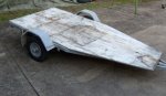
After almost a year, I finally started the necessary mods to turn it into a usable kart trailer which will have the capacity to carry up to 2 karts; apart from the 2" x 2" draw bar, the entire frame is constructed using 1" x 2" SHS, making it really simple to modify...

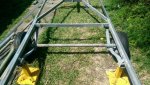
The first thing I needed to do was establish a rectangle base so, wheel arches off, a trip to the local steel merchant & add a 1" x 2" straight rail down each side... that's when I ran into my first problem...

On the left side, there was around 5/8" clearance between the tyre & the new rail; on the right, there was around 7/8" clearance between the tyre & the original rail... :oops:

If I simply move the axle across, I would end up with around 1/4" clearance one each side... not enough for my liking...

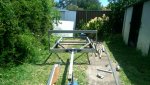
I considered stretching the axle in the centre but, once I realised there was a small spring locator plate welded to the axle & that the stub axles weren't straight, I decided to bite the bullet & replace the entire axle, using the original stubs...

Coincidently, I just happen to have a length of pipe exactly the right size...sitting right next to the trailer (that's where it was "stored")

After cutting the stubs from the axle tube, leaving a small length as a base point, I squared off the ends on the lathe, cut one end of the tube square & welded the two together...

Now to trial fit, measure, cut & weld the other end...
 

Attachments

  • $_58.JPG
    $_58.JPG
    42.6 KB · Views: 24
  • $_598.JPG
    $_598.JPG
    49.4 KB · Views: 22
  • IMAG0263[1].jpg
    IMAG0263[1].jpg
    139.5 KB · Views: 19
  • IMAG0264[1].jpg
    IMAG0264[1].jpg
    77.7 KB · Views: 24
  • IMAG0266[1].jpg
    IMAG0266[1].jpg
    42.1 KB · Views: 23
Last edited:

Crashz28

New member
Messages
33
Reaction score
0
Location
Houston, Tx
I don't about your neck of the woods but you can buy the spring locator plates pretty cheap or take a cut off wheel and chop them off and move them where you need them!

Other wise awesome project!

I was thinking about swapping out my trailer axle to a axle less setup basicly a hub/spindle on each side. I have a 5x8 enclosed trailer that I have to let the air out of the tires to fit it in the garage.

Just goes to show sometimes if you want something to fit your needs then you gotta build it or modify it yourself!
 

machinist@large

Active member
Messages
2,856
Reaction score
2
Location
West Michigan, 49331
Looking good so far. And from the photos, if you keep the current spring height it should sit low enough to be nice and stable.

One trick; to help keep the stub end's parallel, remount the hubs and rim's without the tires. Then, block the rims so they can't spin (a piece of channel iron long enough to support both works great for this) and measure the spacing between the bead flanges in one spot on each side (to account for any variations in the rim's). Place your first tacks; measure. Rotate the axle 180°. Measure. Adjust if needed, place second tacks. Measure.

Now here's where a lot of people get confused: rotate the axle 90° and measure. If it's different, record it but don't do anything yet. Rotate the axle 180° from this position and measure again. If you have any discrepancies, it should be a direct mirror in direction from it's opposite. Adjust, check in all four 90° quadrants. Tack, check again.

This process is to help compensate for any straitness issues in the new axle center section. If the axle stubs (as well as the hub's and bearings) aren't concentric one end to the other, you can build in some really frustrating handling issues without even realizing it. And the reason for mounting the rims is to magnify any potential error so you have an easier time measuring it so you can correct it.

This doesn't require massive amounts of tools, just care, patience, and attention to detail.....

:thumbsup: :popcorn:
 

OzFab

New member
Messages
15,615
Reaction score
8
Location
Warwick Qld, Australia
Thanks for the advice, Pat but, too late, axle's done :D I will check it though, just to see how I did; the stubs were a pretty tight fit in the pipe so, here's hoping it'll be close; however, the way I see it, it has to be better than than the OEMs effort; the deciding factor to replace the axle came when I spun the axle after I split it, with the wheels sitting still, the axle had around 1.5" of runout over 2'... I must be closer than that...

I don't about your neck of the woods but you can buy the spring locator plates pretty cheap or take a cut off wheel and chop them off and move them where you need them!

Already sourced :thumbsup:

Other wise awesome project!

Thanks :cheers2:
 

Attachments

  • IMAG0268[1].jpg
    IMAG0268[1].jpg
    140.3 KB · Views: 15

OzFab

New member
Messages
15,615
Reaction score
8
Location
Warwick Qld, Australia
AH, so that's why I didn't find it funny :roflol:

Honestly, I would be happy with a 300M straight stretch of flat bitumen... I'm not fussy...
 

Poboy kartman

Senior Moments Member
Messages
12,461
Reaction score
1
Location
White Settlement Texas
AH, so that's why I didn't find it funny :roflol:

Honestly, I would be happy with a 300M straight stretch of flat bitumen... I'm not fussy...

Just to make sure....(you probably know.....but I don't know because you are on another Continen......)

But....they have a restaurant called.....'Outback' here....with a quasi Australian theme....and there slogan is:...."No rules....just right."
 

OzFab

New member
Messages
15,615
Reaction score
8
Location
Warwick Qld, Australia
The other day I realised the centre crossmember was longer than the rear so, no matter what I did, the frame would never be square; because I couldn't source material to act as a sleeve, I cut down a length of the same material to fit inside, then I cut the rear crossmember in the centre to stretch it by around 10mm (3/8")...

Now, because the corners aren't square, I need to pull the rear crossmember parallel to the centre one & hope it works, otherwise, I've wasted my time & will have to remove & replace it...

Also, here's a pic of the whole thing so far...
 

Attachments

  • IMAG0277[1].jpg
    IMAG0277[1].jpg
    73.4 KB · Views: 10
  • IMAG0274[1].jpg
    IMAG0274[1].jpg
    69.4 KB · Views: 7
  • IMAG0273[1].jpg
    IMAG0273[1].jpg
    60.4 KB · Views: 4
  • IMAG0271[1].jpg
    IMAG0271[1].jpg
    71.1 KB · Views: 4
  • IMAG0270[1].jpg
    IMAG0270[1].jpg
    73.4 KB · Views: 4
  • IMAG0278[1].jpg
    IMAG0278[1].jpg
    69.2 KB · Views: 9
  • IMAG0276[1].jpg
    IMAG0276[1].jpg
    114.7 KB · Views: 12

OzFab

New member
Messages
15,615
Reaction score
8
Location
Warwick Qld, Australia
A little more work done over the past few days, axle reassembled after cleaning & priming the springs & U bolts, fitted new spacers (they were $5 for the pair) & new fish plates (U bolt anchor plates, $8 each)...

I also manged to fit & tack the header; the bottom piece was notched out around the existing rails to sit under the new side rails...
 

Attachments

  • IMAG0296.jpg
    IMAG0296.jpg
    95.7 KB · Views: 14
  • IMAG0293.jpg
    IMAG0293.jpg
    92.2 KB · Views: 198
  • IMAG0288.jpg
    IMAG0288.jpg
    76.8 KB · Views: 12
  • IMAG0287.jpg
    IMAG0287.jpg
    164.2 KB · Views: 11
  • IMAG0294.jpg
    IMAG0294.jpg
    88.7 KB · Views: 13
  • IMAG0295.jpg
    IMAG0295.jpg
    113.3 KB · Views: 16
  • IMAG0289.jpg
    IMAG0289.jpg
    152.3 KB · Views: 11
  • IMAG0290.jpg
    IMAG0290.jpg
    136.8 KB · Views: 12

Rickracer

RM250 Race Kart Driver
Messages
673
Reaction score
0
Location
Kissimmee Fl.
What I can see of your welding doesn't look too good? Maybe it's the flux core, or stick welding, but I don't see any grinding marks or clean shiny metal where you've cleaned the metal at the joints. If you grind the metal clean, where you plan to weld, the welds will come out MUCH better....
 

OzFab

New member
Messages
15,615
Reaction score
8
Location
Warwick Qld, Australia
Perhaps not on the centre notches (that piece was in & out 4 or 5 times, which wasn't an easy task so, once it was correct, I just tacked it in place) but, everywhere else is clean &/or is coated with zinc primer... & yes, it's flux core...
 

Rickracer

RM250 Race Kart Driver
Messages
673
Reaction score
0
Location
Kissimmee Fl.
Coated with zinc primer before the weld? Or after? After is fine, before will make it nearly impossible to get a good weld, zinc in the weld puddle is never good....
 

Rickracer

RM250 Race Kart Driver
Messages
673
Reaction score
0
Location
Kissimmee Fl.
So this was ground clean and then sprayed with weld through primer?


I'm really not trying to be critical of your work, but I'm concerned that your welds are not going to hold. :worried2::confused:
 

Rickracer

RM250 Race Kart Driver
Messages
673
Reaction score
0
Location
Kissimmee Fl.
Actually, I did read it, twice... not sure what a panel beater is, but I'd guess a body man? Whole different thing than structural welding, but fine, no problem, I meant no harm, and SAID SO, only trying to help, but I promise, you'll not hear from me again on this topic... :backtotopic:
 
Status
Not open for further replies.
Top