You are using an out of date browser. It may not display this or other websites correctly.
You should upgrade or use an alternative browser.
You should upgrade or use an alternative browser.
Finally...
- Thread starter kibble
- Start date
- Status
- Not open for further replies.
mikeandike
New member
- Messages
- 232
- Reaction score
- 3
Just watch out the wires dont get burnt by the engine. make sure they're protected.
kibble
I banned myself
- Messages
- 2,766
- Reaction score
- 15
Yeah, I'll make sure that there's some sort of a protective covering on the wires. I was actually thinking of running the cables through a small rubber hose or some braided wire.
I was bored at work yesterday so I started looking online and decided that I want to make my kart look like the Mario Kart karts. I finally drew up what I think it should be like after seeing various pictures of the front and back of them. The only thing that I'd probably have to modify is that the karts in the game look a lot shorter that they'd have to be for a real person.
I was bored at work yesterday so I started looking online and decided that I want to make my kart look like the Mario Kart karts. I finally drew up what I think it should be like after seeing various pictures of the front and back of them. The only thing that I'd probably have to modify is that the karts in the game look a lot shorter that they'd have to be for a real person.
kibble
I banned myself
- Messages
- 2,766
- Reaction score
- 15
I used the one's that were recommended on the schematic I found which were: 330kΩ, 1.5 kΩ, 15 kΩ. I'm gonna have to go and modify some of those though because the servo tries to go farther than it really needs to and I don't want the servo to break a gear on the inside or something.
The circuit you linked to was very similar to the one I built except for the fact that I used two individual 555 Ic's and the other schematic used a single 556, which is basically two 555's in one package. I could have built a smaller circuit if I had a 556 available.
The circuit you linked to was very similar to the one I built except for the fact that I used two individual 555 Ic's and the other schematic used a single 556, which is basically two 555's in one package. I could have built a smaller circuit if I had a 556 available.
kibble
I banned myself
- Messages
- 2,766
- Reaction score
- 15
Yes, the 556 is just like having two 555's in one package. It's not easy to describe where each of the resistors goes connected to the IC, you have to look at the schematic for that. On the schematic you can see that there are numbers on each of the wires coming out of the 556, each number represents a pin. Resistors don't have a polarity so they can be connected in either direction. The values for each of the resistors is in the schematic. 100k means 100 kilo ohms or 100,000 ohms. 3k9 is 3,900 ohms. 220 with no letter is just 220 ohms.
I have been working on my frame for the past few days and gotten better at welding in the process. I messed up a bit in a few parts, nothing too bad that I couldn't fix but, so far everything seems pretty stable.
I have been working on my frame for the past few days and gotten better at welding in the process. I messed up a bit in a few parts, nothing too bad that I couldn't fix but, so far everything seems pretty stable.
Attachments
-
 CIMG2367.jpg57.4 KB · Views: 37
cmon I'm not that stupid ")
I meant 300ohms for r3, 100ohms for r5, etc. The reason I'm asking is cause the one I linked to has 2 pots. one for base signal and the other for servo position. I would only like to use one pot, and have a fixed resistor for the base signal pot.
I meant 300ohms for r3, 100ohms for r5, etc. The reason I'm asking is cause the one I linked to has 2 pots. one for base signal and the other for servo position. I would only like to use one pot, and have a fixed resistor for the base signal pot.
kibble
I banned myself
- Messages
- 2,766
- Reaction score
- 15
I'm pretty much uber stupid in electronics.
That's what you said before, I didn't question it. LOL, JK.
Well I don't know exactly what values would give you the best results for your servo but, what I would recommend doing is using the values on the schematic and modifying them to your requirements.
If you're asking about the board that I built then I used 330k for R1, 1.5k for R2 and 15k for R3. For the pin where it says "analog in" I connected the wiper of a 100k pot and connected the other two ends of the pot, one to ground and the other to Vcc.
If you want to have a fixed resistor instead of the pot on the first part of the schematic you linked to then what you might want to do is connect a pot first, adjust it to where it gives you what you want, then measure it with an ohmmeter and see what value of resistance it gives you. After that just find something to match what r2 and r6 add up to and you'll only be using one fixed resistor.
BTW, I'm not THAT good at electronics either. I'm sure there's probably a better way to figure out how to get proper values using math. I usually just play around with the values until something works like I want it to or 'til it bursts into flames
, which doesn't happen very often. I hope this helps out.
kibble
I banned myself
- Messages
- 2,766
- Reaction score
- 15
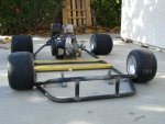
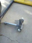
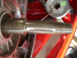
Here's some pics of a mock up of what I eventually want my kart to look like. I just got the tires today through ups. There's a picture of one of the spindles I built and a pic of my engines shaft after I cut out the keyway. I gave my cv joints to a friend who's gonna try to machine them for my application, that's why they're not attached to the diff. Not pictured are the wheel hubs sprockets and pillow blocks that I got on ebay.
Attachments
-
 kartfrnt.jpg82.9 KB · Views: 63
 -
 kartbak.jpg111.1 KB · Views: 55
 -
 kartlow.jpg97.6 KB · Views: 47
 -
 spindle.jpg100.4 KB · Views: 38
 -
 keyway.jpg85.6 KB · Views: 73
2or3wheels
New member
Has that fast look. Are you using pully to jackshat and then clutch on jackshaft?
kibble
I banned myself
- Messages
- 2,766
- Reaction score
- 15
Thank you guys!
Yeah, unfortunately for the time being I'm gonna have to attach the clutch to a jackshaft. I'm using two pulleys of the same size on the engine and on the clutch, the other side will have a sprocket, which I have but is not pictured either. The engine I have doesn't have a 3/4" shaft so the clutch will not fit on it directly.
Yeah, unfortunately for the time being I'm gonna have to attach the clutch to a jackshaft. I'm using two pulleys of the same size on the engine and on the clutch, the other side will have a sprocket, which I have but is not pictured either. The engine I have doesn't have a 3/4" shaft so the clutch will not fit on it directly.
2or3wheels
New member
What size? I know there are ones with 5/8" and 1" too.
kibble
I banned myself
- Messages
- 2,766
- Reaction score
- 15
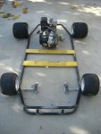
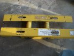
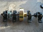
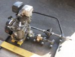
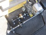
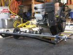
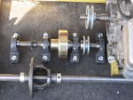
I have some updated pics of my kart. I got an axle for the rear and I put together a mock up of what the rear will be like. I need to buy some more square pipe. The differential is not mounted the way it will be in then end. I just took out the gears and mounted it on the axle so I could get an idea of how much room it would take up and where to put the other stuff.
For those of you wondering, yes, that is an Arrowhead water bottle in between the muffler and air filter. Why? Temporary gasoline container so I could test out the engine. I left it on so that dust wouldn't get into the filter or gas lines.
For those of you wondering, yes, that is an Arrowhead water bottle in between the muffler and air filter. Why? Temporary gasoline container so I could test out the engine. I left it on so that dust wouldn't get into the filter or gas lines.
Attachments
-
 IMG_0001.jpg169.8 KB · Views: 62
 -
 IMG_0002.jpg183 KB · Views: 47
 -
 IMG_0003.jpg188.8 KB · Views: 47
 -
 IMG_0004.jpg177.2 KB · Views: 52
GoAlterBridge
New member
- Messages
- 197
- Reaction score
- 0
That kart's gonna' fly!
- Status
- Not open for further replies.