Engine Sim Software

Status
Not open for further replies.

bob58o

SuckSqueezeBangBlow
Messages
9,646
Reaction score
1,865
Location
Chicago-town USA
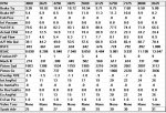
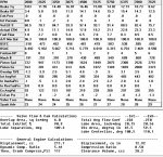
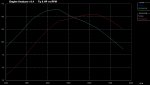
EDIT: Found and fixed my problem.

I changed carb cfm to 1000.
I changed exhaust diameter to 5".
I changed intake manifold to 4".
I changed intake port diameter to 4"

It caused the friction HP to drop from 10 to 9 at 8625 RPM.
 

Attachments

  • big2.jpg
    big2.jpg
    133.3 KB · Views: 8
bob58o

SuckSqueezeBangBlow
Messages
9,646
Reaction score
1,865
Location
Chicago-town USA
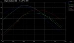
Going back to the original dimensions...
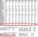
Here's a report that the software generates....

Analysis Report for Mild Street Engine with Desired HP Peak at 6500 RPM

Peak Tq =16.8 @ 4250 RPM 1.23 Ft Lbs per CuIn
Peak HP =17.2 @ 6125 RPM 1.26 HP per CuIn

Maximum Tq/CuIn is 1.231 Ft Lbs/CuIn.
This is somewhat high, indicating good performance, but will
produce high cylinder pressures and temperatures.


Maximum Exhaust System Backpressure 'Exh Pres' is 0 PSI.
This is low for a street vehicle with a full exhaust
system. This is simulating either an extremely free flowing exhaust
system or open headers or open exhaust manifolds. This may be
illegally loud for street operation.


Maximum Intake Manifold Vacuum 'Int Vacuum' is 1 ''Hg.
This is somewhat high for an engine with an Individual Runner type
intake and is limiting air flow and HP.


Maximum Fuel Flow 'Fuel Flow' is 9.2 lbs/hr GAS.
This is equal to 1.6 gallons per hour of fuel flow.
For an injected engine with one injector per cylinder, you will require
at least 9 lbs/hr injectors.


Mechanical Efficiency 'Mech Eff' is 81 %
at the current Peak HP RPM of 6125 RPM.
This is somewhat low and represents a real power loss in this
engine's current operating range. This can be improved by paying
close attention to details in the Short Block Specs menu.


The Intake Valve Mach # 'MACH #' is .604
at your 'Desired HP Peak RPM' of 6500 RPM.
This is somewhat high and indicates you will need more Intake Valve
Diameter, Valve Flow Efficiency or more intake cam profile
(larger Intake Duration, Tappet Lift or Rocker Arm Ratio).


The Maximum Average Piston Speed 'Piston Spd' is 3112 ft/min
at the Performance Calculations Maximum RPM of 8625 RPM.
This is somewhat high (if you want to run this entire speed range),
requiring light, high strength reciprocating components.

A mild street engine should limit PSN SP to a range of 2500-3000 ft/min
with production quality rods. To run at 2750 ft/min or higher, you will
need 'better than production' reciprocating components (connecting rods
& bolts, pistons, etc.).

Maintaining low PSN SP and PSN GS are critical for 'keeping the engine
together'. OVER-REVVING PARTS BEYOND THEIR INTENDED LIMIT IS UNSAFE
FOR THE ENGINE, YOURSELF AND BYSTANDERS.


The Inertia tuning of this intake is tuned to 7973 RPM,
which is much higher than your 'Desired HP Peak RPM' of 6500 RPM.
The engine's breathing may be so restrictive at this point that it
will not be able to take advantage of the inertia tuning. You likely
need longer and/or smaller diameter intake runners.


The % Exhaust to Intake Flow Capacity 'Total Exh/Int %' is 81.5 %.
This is somewhat high, and indicates you could be opening the
exhaust valve too early or you could improve performance by improving
intake valve flow and intake cam profile. The most common 'rule of
thumb' is to design for around 75% EXH/INT flow capability.


IMPORTANT: The Optimize feature at the top of the Main Screen is
an excellent way to find combinations which work well together.
Click on 'Help' in the Optimize screen for tips on this feature.

End of Analysis Report
 

itsid

Moderator
Staff member
Messages
11,563
Reaction score
257
Location
Ruhrpott [Germany]
Wow still a lot of abuse for an engine like that..
Nikasil to the rescue I guess :D

May I ask what ignition you use;
I can't recall any variable ignition system for the gx series and clones..
PVL maybe (haven't looked into it really allegedly it's a true computerized CDI but if it's self advancing IDK)
again just curious.

Mostly since I personally wouldn't care much about highly modified industrial engines
(as a non racer I would rather spend half the dollar for twice the power on a shifted motorcycle engine of course)
Still I think there's a ton to learn from such engine simulation,
for just mildly modded engines and heck even stock ones maybe.

Also nice that you posted that warning messages..
such might carry clues to when and where we should really keep our eyes open and linear speed of reciprocating parts...
and thus conrods and pushrods etc...
Again, if nothing else it reminds you(us) of what to look out for.

:thumbsup:

'sid
 

bob58o

SuckSqueezeBangBlow
Messages
9,646
Reaction score
1,865
Location
Chicago-town USA
May I ask what ignition you use;
I can't recall any variable ignition system for the gx series and clones..


'sid

I don't think the software I have gives me an option for ignition system.

It also seems that the software thinks every engine is going to detonate unless running on high octane gas. It uses the cam specs (along with the other specs) to calculate a cranking pressure. This seems to give a higher calculated cranking pressure than other calculators I've come across.

For example, Grant's 12 :1 engine with 220 duration camshaft running on 100 octane....
If you notice the " * " at low RPMs in the Spark Advance Row, that means that at those RPMs the spark was retarded from possible optimal performance in order to prevent possible detonation. For gasoline, I tend to use 110 octane for every engine even though I know many of them will run fine on lower octane gas.
 

Attachments

  • preignition.jpg
    preignition.jpg
    189.1 KB · Views: 6

c-gar

same as it ever was
Messages
56
Reaction score
1
Location
another part of the world
The closest I can do for a stock engine is going to be the CL1 stage 1 build I showed already.

that's what I asumed...

I still have to guess what number to use for the flow efficiency % and that number is pretty significant. A small change of a few percent makes a pretty big difference.

garbage in, garbage out.

The software also has an option to use actual flow bench data to calculate that number for you.

there's your next project, measuring actual flow data.
 

bob58o

SuckSqueezeBangBlow
Messages
9,646
Reaction score
1,865
Location
Chicago-town USA
there's your next project, measuring actual flow data.

Well I used actual flow data the for the first simulation I did for KartFab.
The builder flowed his 32mm / 28.5mm head. I used 0.150" lift, 0.250" lift and 0.350" lift. The software computed 47.8% flow efficiency.

I also have found some data for a stock Hemi head from another builder with a flow bench.
Using the baseline (unported) numbers for the intake, the software spits out 35.5%. This is in agreement with the Flow % column in the data below.
https://karting.4cycle.com/showthread.php?72908-hemi-head-flow-numbers
 

Attachments

  • hemi flow.jpg
    hemi flow.jpg
    288.5 KB · Views: 7

bob58o

SuckSqueezeBangBlow
Messages
9,646
Reaction score
1,865
Location
Chicago-town USA
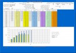
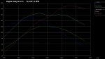
So this shows a Stage 1 Hemi build (using CL1 cam specs because I don't have stock cam specs) and then the same build swapping the carb to something like a 24mm slide carb with 97 cfm.

CL1 camshaft
CR 8.5 :1
Intake Valve 27mm
0.85" Average Port Diameter
2.5" Port Length
35% Intk Port Flow Efficiency
Exhaust Valve 25mm
35 % Ex Port Flow Efficiency
.990 Diameter Exhaust x 18" long
85% Exhaust Pipe Flow Efficiency
1.0 :1 Rocker Arms
 

Attachments

  • cl1 97cfm.jpg
    cl1 97cfm.jpg
    127.9 KB · Views: 8

bob58o

SuckSqueezeBangBlow
Messages
9,646
Reaction score
1,865
Location
Chicago-town USA
This shows the same stage 1 Hemi Build.
One with a CL1 cam and the other with a Mod2.
Both with a stock carb.
 

Attachments

  • cl1 vs mod2.jpg
    cl1 vs mod2.jpg
    129.6 KB · Views: 5

bob58o

SuckSqueezeBangBlow
Messages
9,646
Reaction score
1,865
Location
Chicago-town USA
This shows that engine first with a stock carb and CL1 cam.
Then it shows it with a 24mm slide carb and Mod2 Cam.
 

Attachments

  • cl1 stock vs mod2 24mm.jpg
    cl1 stock vs mod2 24mm.jpg
    124.1 KB · Views: 5

bob58o

SuckSqueezeBangBlow
Messages
9,646
Reaction score
1,865
Location
Chicago-town USA
This shows same Hemi engine.
First with stock CR, Stock Carb, and CL1 cam.
Then with 10 :1 CR, 24mm slide carb, and Mod2 cam.
 

Attachments

  • stock cl1 vs 24mm mod2 10CR.jpg
    stock cl1 vs 24mm mod2 10CR.jpg
    135.3 KB · Views: 1

bob58o

SuckSqueezeBangBlow
Messages
9,646
Reaction score
1,865
Location
Chicago-town USA
This one shows the same engine again.
First Stock CR, Stock Carb, Stock Ports, Stock valve size, and CL1 cam.
Then with 10 :1 CR, 24mm Slide Carb, Port Diameter enlarged from 0.85" to 1.0", Intake Valve increased from 27mm to 28.5mm, Mod2 Cam, and Port Flow Efficiency % Increase from 35 to 40%.
 

Attachments

  • headwork.jpg
    headwork.jpg
    139.5 KB · Views: 3

bob58o

SuckSqueezeBangBlow
Messages
9,646
Reaction score
1,865
Location
Chicago-town USA
Alright you get the picture.
This time I added 1.3 Ratio Rockers Arms to the engine above.

10:1 CR
Mod2
28.5mm Intake Valve
1" average Port diameter
40% flow efficiency
24mm slide carb
1.3 :1 Ratio Rocker Arms
 

Attachments

  • 1.3 ratio rockers.jpg
    1.3 ratio rockers.jpg
    144.6 KB · Views: 5

bob58o

SuckSqueezeBangBlow
Messages
9,646
Reaction score
1,865
Location
Chicago-town USA
And for the final installment of this series....
I swapped the Mod2 for an NR 285-0611, but kept everything else the same as the previous sim, shown directly above.
That has 250 duration, .285" lift, 106 Intake CenterLine, 111 LSA.

Chances are you can't run that cam in a Hemi with 1.3 Rockers without running into clearance issues, but if you could.....
I was just trying to give an idea what kind of difference the cam could make.

I was asked to show Stage 1 mods vs Stage 2 and so on..... I figured this method of comparisons did about that. It shows cam swaps, carb swaps, ratio rockers, CR increase, Valve size increase, port work,...

Anyway it shows going from about 12HP (which seems kind of high to me for a stage 1 with CL1 cam) to almost 23 HP and shifted peak power from about 5k RPM to almost 8k RPM.
 

Attachments

  • 285-0611.jpg
    285-0611.jpg
    143.9 KB · Views: 8

c-gar

same as it ever was
Messages
56
Reaction score
1
Location
another part of the world
You are having way too much fun with this.

I was asked to show Stage 1 mods vs Stage 2 and so on..... I figured this method of comparisons did about that. It shows cam swaps, carb swaps, ratio rockers, CR increase, Valve size increase, port work,...

Anyway it shows going from about 12HP (which seems kind of high to me for a stage 1 with CL1 cam) to almost 23 HP and shifted peak power from about 5k RPM to almost 8k RPM.

I think that's a good comparison of relative benefits for each change. And if the flow efficiency numbers are making big differences, I may try working off the rough edges in the head ports.
 

bob58o

SuckSqueezeBangBlow
Messages
9,646
Reaction score
1,865
Location
Chicago-town USA
And if the flow efficiency numbers are making big differences, I may try working off the rough edges in the head ports.

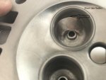
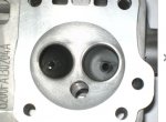
I really have no idea how to port these heads. I just do what I think might work. Without a flow bench, I'm really just guessing (and most likely making it worse. LOL). I tend to look at pictures and try to make em look like what I see.

Many engine builders recommend upgrading the carb. Told me it is one of first things to do if you want to make good HP.

Jody from ARC put out a video on what to do for a basic port job.
Most of the benefit, IIRC, comes from taking the edge off of the short side radius and a good valve job. But I feel like I spend most of my time working the area around the valve guide.
https://www.youtube.com/watch?v=rj8V9wiOh40

KartFab has a video too.
https://www.youtube.com/watch?v=r99XisKXgAw
 

Attachments

  • portwork.jpg
    portwork.jpg
    329.3 KB · Views: 4
  • NR Head.jpg
    NR Head.jpg
    53.4 KB · Views: 4
  • Intake port area of concern.jpg
    Intake port area of concern.jpg
    7.6 KB · Views: 20

KartFab

Active member
Messages
3,381
Reaction score
60
Location
Dallas, TX
heres another one:

Bore? 70mm
Stroke? 55mm
Rod Length? 3.308"
Head Type? stock, untouched, non-hemi predator 212
Flat Head, Wedge, or Hemi
Compression Ratio? 8.5:1 IIRC

Valve Size? stock non hemi (newest version)
Port Dimensions? no idea
Carb cfm rating? 22 mm mikuni

Exhaust Length and Diameter? unknown, put either both .85" or .990"

Camshaft Intake lobe duration and lift? MOD2 cam see spec sheet here https://www.dynocams.com/catalog/documents/DynoCamsMOD2.pdf
Intake lobe center line?
Exhaust lobe duration and lift?
Lobe separation Angle?
Rocker Arm Ratio? stock non hemi parts, possibly champion rockers?

100 octane gas

There's more too, but I should be able to work with that.
 

bob58o

SuckSqueezeBangBlow
Messages
9,646
Reaction score
1,865
Location
Chicago-town USA
OK,
70mm Bore
55mm Stroke
3.308" Rod
Non-Hemi Head = Wedge (I think wedge would be the best way to describe it - Not a hemi, Not a flat-head)
8.5 :1 CR
27mm Intake Valve
25mm Exhaust Valve
Average Port Diameter = 0.85" (Guessing)
Port Length = 2.5" (Guessing)
Port Flow Efficiency % = 35.5 (Using the data I have for a Hemi Head - should be similar)
Manifold = Typical Short Individual Runner (Motorcycle)
Carb CFM = 88
Exhaust Length = 18"
Exhaust Diameter = 0.85"
Exhaust Flow Efficiency = 85% (Guessing)
Intake Lobe Lift = 0.225"
Intake Duration = 245.7 degrees
Intake Lobe Center Line = 108.5
Intake Lash = 0.004" (smallest it lets me pick)
Exhaust Lobe Lift = 0.231"
Exhaust Duration = 245.5 degrees
Exhaust Lobe Center Line = 110
Exhaust Lash = 0.004" (smallest it lets me pick)
LSA = 109.3
Rocker Arm Ratio = 1.05 :1 (I've read anywhere from 1.0 to 1.1 so I hit the middle with 1.05 :1)
100 Octane

15.7 HP at 5750 RPM.
Reasonably similar to the Hemi I showed with a 24mm Carb and Mod2 Cam.
I used 1.05 Ratio for these Rockers (instead of 1.0) and used 35.5 % (instead of 35.0%) flow efficiency, so the peak HP is a little higher even though the carb is a bit smaller.
 

Attachments

  • 22mm Mod2 Gen3.jpg
    22mm Mod2 Gen3.jpg
    110.6 KB · Views: 3
  • 22mm Mod2 Gen3 chart.jpg
    22mm Mod2 Gen3 chart.jpg
    178.3 KB · Views: 3

bob58o

SuckSqueezeBangBlow
Messages
9,646
Reaction score
1,865
Location
Chicago-town USA
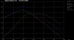
Exactly the same, but with .990" Exhaust Port Diameter.
This might change the Exhaust Pipe Flow Efficiency %, but since I didn't how it would change - I kept it at 85%

For the overlapped graphs - Current = 0.85" Exhaust Pipe, Last Results = 0.99" Exhaust Pipe
15.4 HP at 6375 RPM
 

Attachments

  • 99.jpg
    99.jpg
    110.5 KB · Views: 4
  • 99 chart.jpg
    99 chart.jpg
    184 KB · Views: 6
  • overlap.jpg
    overlap.jpg
    118.5 KB · Views: 5

bob58o

SuckSqueezeBangBlow
Messages
9,646
Reaction score
1,865
Location
Chicago-town USA
And If I let the software optimize the diameter of the 18" Long Exhaust Pipe to produce max peak HP, it picks 0.887"
Here is with 18" X 0.887" Inner Diameter Pipe.
15.8 HP at 5750 RPM
 

Attachments

  • 887.jpg
    887.jpg
    112.7 KB · Views: 3
  • 887 chart.jpg
    887 chart.jpg
    181.4 KB · Views: 5
Status
Not open for further replies.
Top