Electric Mobility Scooter - ETV

JagLite

Member
Messages
50
Reaction score
0
Location
Anchorage, Alaska
Electrical connection questions

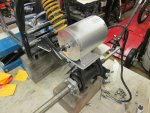
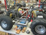
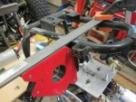
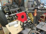
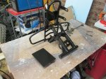
And the motor mount plate trimmed to size:
IMG_3620.JPG

IMG_3621.JPG

IMG_3627.JPG

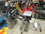
If I don't use a jackshaft I would run the chain (or belt) down and use spacers under the motor for tensioning.

But the speed/gearing calculator tells me I will have to use a jackshaft to keep the top speed down to where I want it to be at around 10 mph.

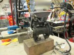
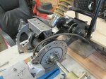
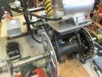
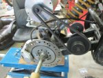
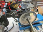
The jackshaft bearing plates will get welded to the swingarm in front of the shock or if necessary to the underside of the swingarm in the same location.

The motor will be oriented the other way with the output sprocket on the right side which I believe will mean the motor wiring will run as it comes with a clockwise sprocket rotation.

Now my wiring question, the connectors wired to the controller are labeled:
Hall
Throttle
Brake
Brake
3-Speed
Indicator Light
E-Lock
Brake Light
Charge
Reverse

If I am understanding what has been posted in other threads for this controller, I will use:
Hall
Throttle
3-Speed
E-Lock (for ignition key/switch)
Reverse

I do not need to do anything with the connectors marked:
Brake
Brake
Brake Light
Charge

Am I correct, and if not, what am I missing?
My batteries will be charged separately.
 

JagLite

Member
Messages
50
Reaction score
0
Location
Anchorage, Alaska
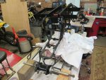
Back together again

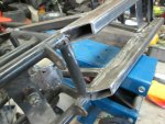
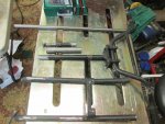
Today I welded on the caps for the bottom frame rail stiffeners, lengthened the steering tube, and burned a hole...


IMG_3660.JPG

IMG_3663.JPG

IMG_3662.JPG

IMG_3664.JPG

As is often the case, I forgot to take pictures of the end caps welded in place so use your imagination... :cheers2:

IMG_3659.JPG

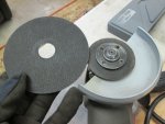
Time for a new cutting wheel, eh?

IMG_3641.JPG

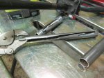
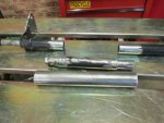
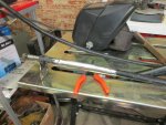
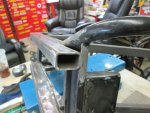
I didn't have a piece of pipe or tube that would fit as the inner sleeve so I sliced a piece of tube and drove it through the new pipe extension then into each end of the steering tube then welded it all up.

IMG_3644.JPG

IMG_3646.JPG

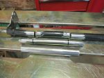
I cut the steering tube in half then cut a piece of the top tubes of the frame for the new steering tube. With an inner and outer sleeve all welded up.

IMG_3649.JPG

IMG_3657.JPG
 

JagLite

Member
Messages
50
Reaction score
0
Location
Anchorage, Alaska
Burning a hole

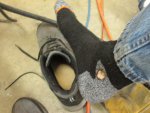
When welding the steering tube I managed to burn a hole...

IMG_3655.JPG

Wow that hurt! :oops:

A piece of molten metal jumped off the steel, went through the slot in the welding table and went into my shoe next to my ankle, Hot! Hot! Hot!
Then I burned my finger when I reached in my shoe to pull the shoe away from my ankle. Yeeeeooooowwweeeee!
First time I've done that.

Which reminds me that last week when I was grinding the frame outside I was surprised at one point how much it was smoking. Then I saw that my shirt sleeve was smoldering. The sparks from grinding had started a fire. I didn't get burned that time, just a charred cuff of my work shirt.

IMG_3666.JPG

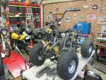
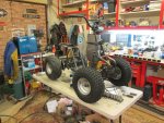
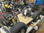
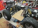
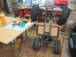
I put the quad back together so I can design the footboards and weld the angle framing in for them. Then cut a plywood floor to screw to the framing.

IMG_3668.JPG

IMG_3669.JPG

Now to order the jackshaft kit and sprockets...

Weld on brackets for the motor controller and start designing the bodywork as well as finding a seat to use. :cool:

Hopefully one of you experienced electric motor users can review the wire connectors I listed earlier and let me know if I am understanding it correctly or not.
 

JTSpeedDemon

2019 Build Off Winner!
Messages
4,026
Reaction score
162
Location
Texas
You're lucky your shoe didn't catch on fire! Since that's a synthetic fiber shoe, it would have melted on to your foot!:eek:
Invest in some leather work boots. You can't be too safe with welding.:(
 

Functional Artist

Well-known member
Messages
5,654
Reaction score
3,293
Location
Toledo, Ohio
If I don't use a jackshaft I would run the chain (or belt) down and use spacers under the motor for tensioning.

But the speed/gearing calculator tells me I will have to use a jackshaft to keep the top speed down to where I want it to be at around 10 mph.

The jackshaft bearing plates will get welded to the swingarm in front of the shock or if necessary to the underside of the swingarm in the same location.

The motor will be oriented the other way with the output sprocket on the right side which I believe will mean the motor wiring will run as it comes with a clockwise sprocket rotation.

Now my wiring question, the connectors wired to the controller are labeled:
Hall
Throttle
Brake
Brake
3-Speed
Indicator Light
E-Lock
Brake Light
Charge
Reverse

If I am understanding what has been posted in other threads for this controller, I will use:
Hall
Throttle
3-Speed
E-Lock (for ignition key/switch)
Reverse

I do not need to do anything with the connectors marked:
Brake
Brake
Brake Light
Charge

Am I correct, and if not, what am I missing?
My batteries will be charged separately.

Your project is lookin' good :thumbsup:

Yup, your wiring plan seems correct :cheers2:

IMO
Before incorporating a "jack shaft", I would try the "direct drive" approach first
…& see what your actual speeds are in low, med & high :2guns:

---------- Post added at 09:35 AM ---------- Previous post was at 09:32 AM ----------

You're lucky your shoe didn't catch on fire! Since that's a synthetic fiber shoe, it would have melted on to your foot!:eek:
Invest in some leather work boots. You can't be too safe with welding.:(

I see "boneheads" on YouTube wearin' shorts-n-flip-plops while weldin', all the time :smiley_omg:
 

JagLite

Member
Messages
50
Reaction score
0
Location
Anchorage, Alaska
Floor supports are in

I cut some angle from an old bed frame and welded it on:

IMG_3704.JPG

Next time will be to make a plywood floor, mount the controller and batteries, and wire it up.

:cheers2:
 

Quinc

Member
Messages
236
Reaction score
1
Project is looking great! What size chain are you planning on running? If going with the smaller 25mm you can get as small as a 10T sprocket off ebay that will fit the motor. (stock that motor comes with 13T)

I would also run the brake switches hooked up. You can use razor mx500/650 hand brakes.(they are well built for the price) This cuts off power to the motor when the brake is used. (Will help if pops happens to whiskey throttle or lets kids ride)

The look you went with reminds me of the Honda Rukus.


JagLite

Member
Messages
50
Reaction score
0
Location
Anchorage, Alaska
Woodwork

Thanks for the information on the brake switch, I wondered what they did.
I will check out the Razor controls too. :cheers2:

I've ordered 10 feet of #35 chain and some master links along with the jackshaft kit and sprockets to play with.


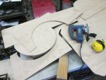
I made a cardboard template for the floor then cut out a piece of 1/2" plywood for the finish floor:

IMG_3714.JPG

IMG_3715.JPG

IMG_3743.JPG

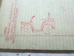
With that on I sketched up what I hope to make the body look like:

IMG_3745.JPG

Not very artistic am I?

Then I pulled out a piece of 1/4" Oak plywood left over from a cabinet job and cut out the sides.

IMG_3748.JPG

I ran out of time to do more and will be out of state for a week or so.

I'll be back! :cheers2:
 

JagLite

Member
Messages
50
Reaction score
0
Location
Anchorage, Alaska
I'm back

I had a most excellent time in Arizona riding trailbikes.

Yesterday was my first shop day and I was able to get a good bit accomplished.

IMG_3897.JPG
Locating and squaring the bearing plates took a bit of figuring.

IMG_3902.JPG
All is good with the bearings, shaft, and sprockets in place.

IMG_3908.JPG
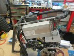
Motor in place it is time to hang the controller.

IMG_3910.JPG
One mount ready to be tacked

IMG_3914.JPG
Second mount ready

IMG_3916.JPG
Controller in place.

IMG_3919.JPG
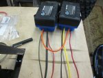
The neat Kobalt battery connectors came with #14 wire.
Reading online some places said 14 is fine for 48v 1,800 watts but other sites called for #10 wire so I replaced the 14's with 10's.
Unfortunately my wire supply shop didn't have any red 10 so I bought yellow and black. Funny thing, the yellow was marked RED on the clear plastic box...

We have 50v now!

IMG_3925.JPG
Wiring the controller to the motor with a connector block.
I have not put the wires from the battery in yet, I will go over all the connections again to double check before powering up.

IMG_3928.JPG
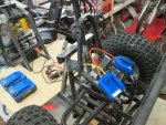
Where the electrical connections will be for easy access.

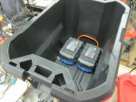
IMG_3929.JPG
Where the batteries will go, (in a storage box).

I checked out the Razor brakes but they are cable operated, the disc brake on this is hydraulic so that won't work.

I think the atv had a rear brake light which means the lever assembly is designed to have a brake switch so I will see what I can find.

Thanks for suggesting it! :thumbsup:
 

JagLite

Member
Messages
50
Reaction score
0
Location
Anchorage, Alaska
How to wire battery monitor?

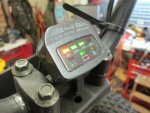
Does anyone know how I should wire the battery monitor I bought?

This one:

IMG_3930.JPG

It has three wires... ?
I thought it would just wire to the hot and cold battery wires.
But the third wire?

I will now search the 'net.
 

JagLite

Member
Messages
50
Reaction score
0
Location
Anchorage, Alaska
Yo!
I found it online, where I bought the monitor actually, I don't know why I didn't see it there when I ordered it...
Just two wires for me, the third wire is for the headlight indicator which I won't be using.
Maybe someday, but not now.
Thanks anyway!
 

Quinc

Member
Messages
236
Reaction score
1
Careful hooking that up directly to the batteries. Might be too many amps for it. There is a cable that comes off the controller called "indicator" that is a voltage output and will come on when you turn the power switch on.
 

JagLite

Member
Messages
50
Reaction score
0
Location
Anchorage, Alaska
Electric mysteries

Careful hooking that up directly to the batteries. Might be too many amps for it. There is a cable that comes off the controller called "indicator" that is a voltage output and will come on when you turn the power switch on.

This is a challenge for me because of the mysteries of electricity.

I wired the battery indicator up to the "Indicator" wires but got nothing.
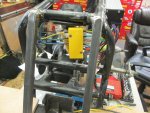
I reversed the wires, still nothing, I checked the wires from the controller and my ohmmeter reads no voltage at all. Actually the meter shows "00.00v" until I touch the wire then it changes to "0-L". I don't know what that is indicating on my ohmmeter but whatever it is it isn't working.

So I moved on to wiring up the fwd/rev handlebar switch which I thought would be easy, only two wires. And it was, sort of. Wired up I turned the key on and sure enough it works! Only the position of the switch is backwards, when the switch is fwd, the motor turns in reverse rotation at lower rpm, when the switch is moved to rev the motor spins in fwd rotation at full rpm.

No problem, I will just switch the wires and that will fix it.
Nope, when I did that the motor turns in rev rotation at reduced rpm when the switch is in EITHER fwd or rev positions???? Huh?

I tired that twice with the same results so I wired the switch to where it gives me both fwd and rev at the correct rpm, even though the switch is backwards. I will make labels to put over the ones on the switch.

Then I decided to put the battery indicator wires in the connector for the fwd/rev switch to see if that would power up the indicator...

More mystery for me, when I did that, not only did the indicator not light up, the motor now only ran in reverse at low rpm no matter which way I set the switch. I don't understand how this works but evidently it is not just a positive/ground wiring system.

I pulled the battery indicator wires back out and the motor went back to correct operation.

I still had no idea if the battery monitor was good or bad so I wired it up directly to the power connection block and installed the battery... It works! It didn't appear to mind the full power of the batteries but I can't turn it off since it is not wired through the key so that won't work.

I think if I wire the power (+) for the battery indicator to the key switch wire after the key (downstream? I don't know the correct term) and the ground wire to ground, then it should work. I think. Maybe? I am scratching my head with this stuff.:huh:

I will wire up the speed range switch tomorrow and I wonder what crazy results I will get with that?

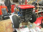
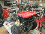
I did find a good front trunk storage box and battery holder:

IMG_3936.JPG

IMG_3937.JPG

IMG_3938.JPG

IMG_3939.JPG
 

JagLite

Member
Messages
50
Reaction score
0
Location
Anchorage, Alaska
Getting closer

Some good, some not so much.

I finished the wiring and everything was working, the battery indicator, fwd/rev, and the high/low speed switch.

Then I rerouted the wiring to the finished location and lost reverse and high speed. I am pretty sure it is my connectors for the wiring because I can disconnect the switches and jump the wires to get reverse and high speed. I believe the switches aren't connecting so the controller is operating in the default mode.

I cut and installed the chains, then installed the wheels and let them spin for a while.

Slowly making progress.

IMG_3961.JPG

IMG_3952.JPG

IMG_3957.JPG

That is the old brake line that is too short to run under the floor.
The new one will be routed below and not near the primary chain.

IMG_3963.JPG

IMG_3964.JPG

IMG_3965.JPG

IMG_3966.JPG

IMG_3969.JPG

I will find a small plastic storage box to put all the wires and connectors in by the controller to clean everything up.
 

Quinc

Member
Messages
236
Reaction score
1
looking good! The wiring is always the worse part on a new controller. After a while you will figure it out. Post a pic of all the connections and labels and we can help you out.
 

JagLite

Member
Messages
50
Reaction score
0
Location
Anchorage, Alaska
I spent yesterday working on the snow blower so I didn't get to do more on the wiring.
I think it is probably just bad connections so I will check continuity of the wires to the switches.
Could be bad switches but I really doubt that since they were working until I moved the wires.
Should be easy to find and fix....

(I've said that many times and it usually hasn't been)
 

JagLite

Member
Messages
50
Reaction score
0
Location
Anchorage, Alaska
All fixed now. :wai:

I stripped the ends of all the wires 10mm as indicated on the back of the connectors and everything works as it is supposed to.

I couldn't see the marking on the little connector until I put on my reading glasses and used a magnifying glass.
A helpful member on a motorcycle forum told me where to look.

I had stripped about 5mm on each wire but it needed to be 10mm.
 

JagLite

Member
Messages
50
Reaction score
0
Location
Anchorage, Alaska
More progress this weekend:

IMG_4016.JPG

IMG_4017.JPG

IMG_4019.JPG

Painting the frame.
I just used a 1" brush and a can of Rustoleum satin black paint.
Nothing fancy, just protecting it from rust, making it look finished, and cleaning it up. More painting tonight hopefully to get it all coated.

Still to do is a seat and the bodywork. :thumbsup:
 
Top