Drift trike build Log

Status
Not open for further replies.

tinamcjittles

ello m8
Messages
391
Reaction score
0
Location
Allovau
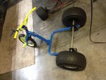
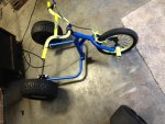
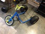
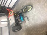
Sup bros! It all started when my neighbor threw away his bike.. It was a 10 year old kid's bike, but you couldn't really tell anymore lolzz
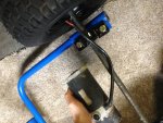
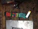
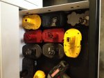
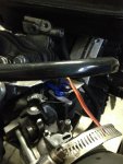
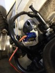
Regardless, It will be electric. I'm using cr18650 cells that were scavenged from laptop batteries.. A hecka lot of them too; 24 to be exact, and as a backup supply I will wire a second pack consisting of 4 drill batteries! It will have two electric motors as well, one from a mobility scooter, and one from a craftsman battery powered saw.... It basically will have a small low power drivetrain and a high-torque, high-speed drivetrain! It will be so sick! Anyways, here's the pics as of now
(Everything except the wheels is from the trash)
Edit: I can't fix the typo in the title...
 

Attachments

  • image.jpg
    image.jpg
    353.3 KB · Views: 17
  • IMG_0180.jpg
    IMG_0180.jpg
    391.5 KB · Views: 12
  • IMG_0178.jpg
    IMG_0178.jpg
    397.9 KB · Views: 16
  • IMG_0176.jpg
    IMG_0176.jpg
    443.9 KB · Views: 13
  • IMG_0177.jpg
    IMG_0177.jpg
    404.6 KB · Views: 14
itsid

Moderator
Staff member
Messages
11,563
Reaction score
247
Location
Ruhrpott [Germany]
me cans fixed ;)

Now.. laptop cells.. drill batteries... mixed motors... uh tina...
I don't hear too many good things, do I?

Anywhoo.. please proceed but don't rush, and when in doubt, please ask!
For now.... :popcorn:

'sid
 

tinamcjittles

ello m8
Messages
391
Reaction score
0
Location
Allovau
me cans fixed ;)

Now.. laptop cells.. drill batteries... mixed motors... uh tina...
I don't hear too many good things, do I?

Anywhoo.. please proceed but don't rush, and when in doubt, please ask!
For now.... :popcorn:

'sid

Lol thanks :D
It's fine, more experience in electronics than go karts actually :lolgoku:
the cells have a low C rating :/
I'm dividing them into series of three, then stringing the whole lot together in parallel.. The drill batteries are going to be put in series for high speeds! It will have three speeds technically, high speed being drill batteries, medium being half of the drill batteries, and slow/high torque being all of the li-ions...
It will be really cool because at any one speed you're never using the same batteries, meaning if one set runs low, just run at a different speed!

My goal is to have a vehicle that can charge with solar panels so I can't be stranded; ever! The saw motor will be the low torque/high speed drivetrain later on when the other stuff is done

The plan was to use supercapacitors but I need to order some acids and electrolytes to make anything useful for now (although I did make some supercaps, but the voltage was pathetic ~.6V @ 10F (1" x 1" squares))

Totally open to any ridiculously innovative ideas, I know you blokes have a bunch :idea2:

PS; It'll be brushless when I get a job.
 

tinamcjittles

ello m8
Messages
391
Reaction score
0
Location
Allovau
Wanted to post an update because this is the current project again.
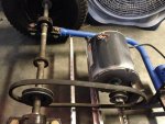
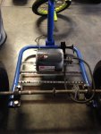
Got an industrial AC fan motor (induction), so If all goes well there'll be a nice tutorial on how to make a DIY DC-AC motor controller. Speed can be controlled by frequency, amplitude and duty cycle, so I'll be using an arduino to drive the logic level 5 volts into a MOSFET H-bridge. The frequency will be controlled by a potentiometer in the pedal that's read by the arduino; the arduino's delay will be a floating variable so that control is really percise.. It will have to be divided by a function so that it's lowest is 60 Hz (about 6-7 ms) and highest is maybe double that so it can reach a wider speed range. A fun project to learn about these old AC induction motors because you can see how each of the pieces of iron in the core is spaced so that it stays a nice constant speed at 60 Hz.
Paragraphs aside, here are the pics of the frame design and batteries so far :D

Edit:
unless by some sorcery this ratio actually moves me in the end, it will be changed lol
 

Attachments

  • tinatinatina 020.jpg
    tinatinatina 020.jpg
    311.6 KB · Views: 6
  • tinatinatina 019.jpg
    tinatinatina 019.jpg
    378.8 KB · Views: 9
  • tinatinatina 018.jpg
    tinatinatina 018.jpg
    345.6 KB · Views: 10

Redlig

Member
Messages
85
Reaction score
0
First electric rear wheel drive I have ever seen. Only commenthe I have is that I know what 18650s are my vaporizer takes a few of them haha
 

outcrydrummer

KART ART
Messages
364
Reaction score
0
Location
Greensboro, NC
I'm not sure a v belt is going to drive you anywhere........or anywhere in a hurry. From my experience they don't drive things very well under load.......You probably need a chain drive or at the least a cog belt.
I could be wrong but............... never mind I'm never wrong.
LOL
 

outcrydrummer

KART ART
Messages
364
Reaction score
0
Location
Greensboro, NC
Wanted to post an update because this is the current project again.
Got an industrial AC fan motor (induction), so If all goes well there'll be a nice tutorial on how to make a DIY DC-AC motor controller. Speed can be controlled by frequency, amplitude and duty cycle, so I'll be using an arduino to drive the logic level 5 volts into a MOSFET H-bridge. The frequency will be controlled by a potentiometer in the pedal that's read by the arduino; the arduino's delay will be a floating variable so that control is really percise.. It will have to be divided by a function so that it's lowest is 60 Hz (about 6-7 ms) and highest is maybe double that so it can reach a wider speed range. A fun project to learn about these old AC induction motors because you can see how each of the pieces of iron in the core is spaced so that it stays a nice constant speed at 60 Hz.
Paragraphs aside, here are the pics of the frame design and batteries so far :D

Edit:
unless by some sorcery this ratio actually moves me in the end, it will be changed lol

I'm somewhat understanding the use of the arduino but what is your dad gonna say when he notices all his drill batteries are missing????
 

Redlig

Member
Messages
85
Reaction score
0
I'm not sure a v belt is going to drive you anywhere........or anywhere in a hurry. From my experience they don't drive things very well under load.......You probably need a chain drive or at the least a cog belt.
I could be wrong but............... never mind I'm never wrong.
LOL

Cog belt mcmastercar oh yeah
 

mckutzy

Well-known member
Messages
8,353
Reaction score
109
Location
bc, canada
That's a furnace/fan motor. It needs to have a constant cooling from the air fan it drives or otherwise air flow over it......
Itll burn quickly..... there are much better candidates out there....

..And what are you going to do with the switch inside?
 

tinamcjittles

ello m8
Messages
391
Reaction score
0
Location
Allovau
I'm not sure a v belt is going to drive you anywhere........or anywhere in a hurry. From my experience they don't drive things very well under load.......You probably need a chain drive or at the least a cog belt.
I could be wrong but............... never mind I'm never wrong.
LOL

Unless you're of the female variety that last sentence can't be true :roflol:
I agree very much so lolol, this build was just started as the world's most entertaining recycling adventure, so I'll be harvesting the chain system from some bikes :D

---------- Post added at 02:01 PM ---------- Previous post was at 01:57 PM ----------

I'm somewhat understanding the use of the arduino but what is your dad gonna say when he notices all his drill batteries are missing????

They aren't my dad's :lolgoku:
The company he works for switched to lithium tools and threw out all of the old ni-cad stuff (0% of which made it to the dumpster)...

---------- Post added at 02:04 PM ---------- Previous post was at 02:01 PM ----------

That's a furnace/fan motor. It needs to have a constant cooling from the air fan it drives or otherwise air flow over it......
Itll burn quickly..... there are much better candidates out there....

..And what are you going to do with the switch inside?

Whoa, wait a sec, what switch? o_0
maybe the shear speed will give it the wind it wants ( ͡° ͜ʖ ͡°)

Yeah there are better candidates but you gotta work with what ya got
 

mckutzy

Well-known member
Messages
8,353
Reaction score
109
Location
bc, canada
Most single phase like have a centrifugal switch inside to switch it to run, from the start cap bump.
Something tells me your not going to get far without already knowing single phase motors have switches.... Let alone using an Arduino as a frequency drive...

If anything a 3 phase would be a better start... Not a single...
 

tinamcjittles

ello m8
Messages
391
Reaction score
0
Location
Allovau
Most single phase like have a centrifugal switch inside to switch it to run, from the start cap bump.
Something tells me your not going to get far without already knowing single phase motors have switches.... Let alone using an Arduino as a frequency drive...

If anything a 3 phase would be a better start... Not a single...

So it kind of de-synchronizes the crests and troughs to make the rotor move in a specific direction. I'm doing this project to learn about this kind of thing so I'm not going to spend $100 on a 3 phase this size just to avoid some effort.. But I'm looking for some mosfets that can handle this kind of current and also gotta get some NPNs for it. It will have to feed the frequency into a transformer to get that nice waveform and maybe even some inline caps; the efficiency losses aren't bad for those things but it makes me wonder what the range will be like
 

tinamcjittles

ello m8
Messages
391
Reaction score
0
Location
Allovau
On the go kart I just installed an electric throttle system. Now it has cruise control, electric adjustable idle, and no more pedal! Although the kill-switch is there as well just in case :D

I just had to map the endpoints to fit nicely with how far I want the throttle to be able to travel
 

Attachments

  • PotServo 007.jpg
    PotServo 007.jpg
    304.4 KB · Views: 9
  • PotServo 006.jpg
    PotServo 006.jpg
    322.8 KB · Views: 9
  • PotServo 004.jpg
    PotServo 004.jpg
    372.4 KB · Views: 10
  • PotServo 002.jpg
    PotServo 002.jpg
    361.3 KB · Views: 9

tinamcjittles

ello m8
Messages
391
Reaction score
0
Location
Allovau
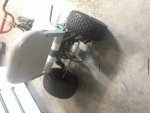
So just as an update to where all this was left.. In random intervals I've made progress, then lost more (on repeat) until what you see it looks like now. I will say it did look pretty nice at one point but was too slow so tore it back down and re-did batteries, control circuitry, etc..

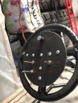
So to explain the pictures: it has a boat seat because the bike seat was painful and made it look even worse, got a red and black paint job because the little kid colors were repulsive, had/has a 555 PWM based throttle (potentiometer sticking outta handlebars), has turf tires for maximum awesome, a ~17:1 gear ratio using jackshaft, a 1HP brushed DC treadmill motor rated for 95v... Just whatever was lying around

Electrics:
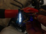
2s2p 20V drill battery pack tied to 3s5p LiIon pack (lots more in the mail) which gets about 54-56 volts max and around 25 Amps (~1.4KW). The positive end goes into the motor and low side switching is done through various plug and play parallel MOSFET banks that I'm testing, those are controlled by a derivative of some generic MOSFET driver circuits that I sketched up because this microcontroller operates at 3.3v and is active low. The power has gotten to such a ridiculous level at this point that I've resorted to a pair of IRFP260n MOSFETs for lower on resistance and upped the gate voltage/current peak! The microcontroller is an ESP8266 nodeMCU, (which only has one ADC interface pin so a separate BMS is in the works) which is used to drive the .96" OLED display, calculate PWM duty cycle from accelerometer input, read battery voltage to prevent damage, and hopefully in the future monitor current, temperature and whatever else sounds like fun..


Problems... of course
Right now it works great, but top speed is very slow because of gearing and voltage. The most annoying issue is dead MOSFETs, while the control circuitry is as efficient as possible, the FETs can't seem to handle more than 40 volts for whatever reason! It is driving me insane to troubleshoot because changing them out for higher power components has no new effect. It must be the driver circuit but I'm more interested in what equations I could use to explain the issue in terms of gate to source voltage, and turn on time in nanoseconds for the driver <-(which must be the problem)
All of this is to be expected while reinventing all the wheels humanly possible in controlling brushed motors but how else will I learn if not by wasting money on roasted parts?! lolol


Funny story though, my neighbor took it off-roading and the MOSFET overheated; this jammed the motor at full power whilst the little 12 year old was trying to hold on for dear life to unplug the battery.... Dude that kid got dragged across my neighbor's (was perfect) yard for so long before reaching that connector :roflol:


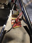
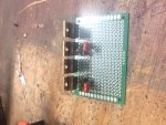
The bottom pic is of a MOSFET H-bridge with the driver circuitry on board that I want to use for a brushless/induction motor, really interesting motors that don't see much use in electric vehicles for lack of research funding but have huge potential in both efficiency and in the virtually infinitely variable magnetism of the ferrous core. Tesla's website literally says that they are better than brushless motors in every way but would cost too much in R&D to implement effectively.
 

Attachments

  • IMG_1249.jpg
    IMG_1249.jpg
    354.6 KB · Views: 10
  • IMG_1250.jpg
    IMG_1250.jpg
    339.3 KB · Views: 7
  • IMG_1251.jpg
    IMG_1251.jpg
    299.7 KB · Views: 8
  • IMG_1252.jpg
    IMG_1252.jpg
    226 KB · Views: 7
  • IMG_1253.jpg
    IMG_1253.jpg
    353.7 KB · Views: 8

tinamcjittles

ello m8
Messages
391
Reaction score
0
Location
Allovau
Just swapped out the MOSFETS with a pair of 1200V 25A IGBTs to see the difference; they were able to handle 60 volts for a few minutes but when I held the trike stationary and pinned the throttle (stall current test) they fried after a few seconds. Strangely they were hardly warm, but were passing a PWM signal at > 40A and 60V.. 2.4KW isn't bad IMO. Anyways, I would order larger yet IGBTs, but I want to give a cheap SSR a try, based on a TRIAC and can handle 60V 40A (125A pulsed).


This issue is driving me nuts but the UI on the speed/duty cycle/voltage readout is looking pretty nice so far.

Sorry that this is a lot of techy minoosha but someone somewhere will appreciate not having to burn money in fancy MOSFETs and IGBTs because they read this..
Also, Sid if you have any ideas for driving ridiculous currents LMK, I'm leaning towards a bank of MOSFETs that are impedance matched and driven with large gate currents for low switching losses and low heat.
 

itsid

Moderator
Staff member
Messages
11,563
Reaction score
247
Location
Ruhrpott [Germany]
Yeah, sorry.. variac is not exactly something I'd call an arduino to help for..
that 200lbs shop gorilla (who's -as you know- a huge fan of variac drives and arduinos might be the one to ask ;))
Sorry, from on top of my head I have no idea really..
but I'll think about ...

for now I'm with mckutzy a different motor might be the easiest solution (a universal motor
would only need a boosting circuit since it takes DC power as well as AC... 1600W leafblower 30 bucks new... 'nough power ;) no money' or as he said a three phase and just copy some RC ESC setup)
I will have to get those easy solutions out of my head first ;)

'sid
 
Status
Not open for further replies.
Top