Diamonite Electrathon America Racer

Denny

Canned Monster
Messages
11,634
Reaction score
8,073
Location
Mayberry, Indiana
I saw years back someone did an experiment with beer cans as crumple zones behind car bumpers. What looked to be like a good idea on the surface turned out to not work. New but sealed cans were too rigid. New sealed cans but dented were too soft. Open cans were also too soft. Sealed but standing up not dented too soft. The point is there just was no happy place. The cans either reacted too slowly or too quickly. And that was just a one time use deal.
 

Functional Artist

Well-known member
Messages
5,350
Reaction score
2,841
Location
Toledo, Ohio
Mr. FA... I had a realization last night. While using my own analog bathroom scale , I noticed if I centered my weight, stepped right in the middle, I had very inconsistent readings. I have to keep even pressure on the sides to get an accurate reading.
Idk, just something to look into.
Hey Edwin,
Interesting...next time maybe a good idea to use a "spreader plate" on the scale :thumbsup:

Thanks for the input :cheers2:
 

Functional Artist

Well-known member
Messages
5,350
Reaction score
2,841
Location
Toledo, Ohio
I think that scientists and engineers have sort of set a reasonable president that closed cell foam is not necessarily a substitute for a spring/airbag/hydraulic device. I like how you think though FA, you know I love ya.
Hey EZ,

Feeling is mutual...my friend...as we have been "workin' together" for a very long time :sifone:

IDK the concept seems to have some merit...ta me
...at least IMO enough to warrant some "real world" testing :2guns:

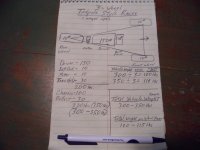
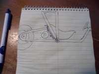
Some more info drawed out :)

* Notice, this racer should only be 300-350lbs. (total)
...& there should only ~100lb. per suspension/wheel :thumbsup:
SAM_6530 (1).JPG
 

Functional Artist

Well-known member
Messages
5,350
Reaction score
2,841
Location
Toledo, Ohio
Maybe it’s time you took one of your other karts and used it as an engineering mule. Modify the rear suspension to use your new idea as a proof of concept.
Hey Denny,
Hmmm...I could probably "swap out" (technical term) the rear suspension (riding lawnmower seat springs) on my Damien kart for (1) &/or even (2) layers of the Closed Foam material :cheers2:

But, I kinda think "we" can anticipate what the outcome of those tests would/should be ;)

Here is a quick reminder of the construction of Damien (~6 years ago)
...& it has some pretty good visuals of the rear suspension design & materials too :thumbsup:

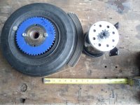
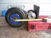
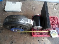
*Notice that besides the motor, the battery pack is also mounted on the trailing arm (increasing the unsprung weight)
 

Functional Artist

Well-known member
Messages
5,350
Reaction score
2,841
Location
Toledo, Ohio
Love your tenacity FA.
Now you have a baseline of data for foam squish.
Hey WTR,

Thinkin' about everything...I may have had some data "mixed up
...but, I thikn I got 'er more better organized...now ;)

* This is another reason I "jabber" & "post"...so much :innocent::devil2:

It helps me to think things thru...more better :cheers2:
...& by openly discussing "things"
...evaluating comments from "peers"
...& then, re-analyze & re-access

I (hopefully) get a better "grasp" & understanding :cornut:
SAM_6594 (1).JPG
At what proportion will 100 lbs of kart be held with 7 psi of foam?
IIRC the 8lbs. reading was only for (1) 2" x 2" x 1" (thick) square sample
...but, "if" (for example) "we" used a 6" x 6" pad (which would consist of (9) of the 2" x 2" x 1" squares)

According to our data, a single layer of 6" x 6" x 1" thick pad, could/should support
...~450 lbs. (with only ~1/2" of) "drop"
...& up to ~1,980 lbs. (max)
&
If "we" double it up to (2) of the 6" x 6" x 1" layers they could/should be able to support
...~72 lbs. (with only ~1/2" of) "drop"
... ~360 lbs. (with 1/2" of drop)
...& IDK...much more (as a max) :2guns:
 

Functional Artist

Well-known member
Messages
5,350
Reaction score
2,841
Location
Toledo, Ohio
More random
...& maybe sometimes "on topic" drawins' :sifone:

Trailing Arm with coil-over shock suspension
...& motor placement options
SAM_6588 (2).JPG
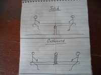
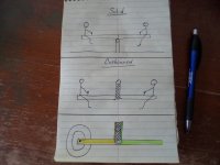
A Teeter-Totter (with solid &/or cushioned options)
SAM_6589 (1).JPG
Adjust/arrange & extend the (above) concept to/for a go kart rear suspension ;)
SAM_6591 (2).JPG
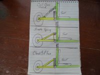
Here is an illustration of some suspension options

Top: standard coil-over shock
Mid: Riding Lawnmower seat suspension springs
Bottom: Closed Cell Foam insert
SAM_6593 (2).JPG
 

Functional Artist

Well-known member
Messages
5,350
Reaction score
2,841
Location
Toledo, Ohio
Love your tenacity FA.
Now you have a baseline of data for foam squish.

Now let's move on to levers.
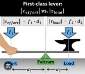
A simple mechanism for multiplying force.

View attachment 159001

At what proportion will 100 lbs of kart be held with 7 psi of foam?
Hey WTR,

As far as "leverage" is concerned
...shorter is better?...right? :unsure:
&
This is about as "short as it gets" (while keeping the motor down low)
...looks like maybe ~12" from axle to pivot point
...& maybe ~10" from axle to motor shaft

* Shorter also means
...less trailing arm material is required
...& the chain will be shorter too
...which = less weight :)
SAM_6568 (1).JPG
Mocked up would look like this :thumbsup:

* Notice how the motor
...could mount to the back side of the "pad" backer
...making that "part" of the trailing arm "dual purpose" :wai:
SAM_6574 (1).JPG
Top view
SAM_6575 (1).JPG
In drawin' form :2guns:
SAM_6473 (1).JPG
Back to the data
These "numbers" should be able to be manipulated
...with differing shapes, amounts, sizes & layers
...of the Closed Cell material ;)
SAM_6594 (1).JPG
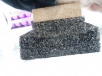
Like in this "crush test" for example

I noticed that when using a smaller piece of foam
...on top of a larger piece
...they "shared" the pressure differently
...as the larger piece didn't "crush" evenly
...like it did, when both pieces were the same size :cornut:
SAM_6533 (1).JPG
 

Whitetrashrocker

Inmate #952016
Messages
4,665
Reaction score
3,770
Location
Southern New Mexico
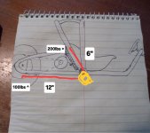
Lets see if I got this right.

Screenshot_20251224_092550_Chrome.jpg

Orange is a pivot I'm assuming, and red would be a solid rear swing arm? (Simplified drawing)
Thats a 2:1 lever.

I think you need to turn your lever around. Make the wheel on the short side and the foam on the long side. Then that same 100lbs would be 50lbs at the foam. As a downfall your upright part would now be 24" up in the air behind your head rest

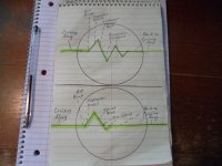
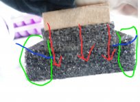
Your foam test.
Red arrows are force.
Green areas are under no load.
The blue lines would be slight resistance due to deflection/ deformation.

Screenshot_20251224_092604_Chrome.jpg
 

Functional Artist

Well-known member
Messages
5,350
Reaction score
2,841
Location
Toledo, Ohio
Lets see if I got this right.

View attachment 159065

Orange is a pivot I'm assuming, and red would be a solid rear swing arm? (Simplified drawing)
Thats a 2:1 lever.

I think you need to turn your lever around. Make the wheel on the short side and the foam on the long side. Then that same 100lbs would be 50lbs at the foam. As a downfall your upright part would now be 24" up in the air behind your head rest
Hey WTR,

Yup...sound about...right :thumbsup:

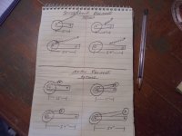
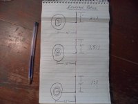
For personal "clarity" I drew out some leverage options
...& here is some figurin' data/notes...commentary ;)

If using a ~6" "pad"
...the ~12" swing arm would have a ~2:1 leverage advantage, over a ~6" backing plate
...&/so, a 2:1 ratio would convert (turn) that ~100 lbs. into seeming like ~200 lbs.

If using a ~9" "pad"
...the ~12" swing arm" would have a ~1.5:1 leverage advantage, over a 9" backing plate
...&/so, a 1.5:1 ratio would convert (turn) that ~100 lbs. into seeming like ~150 lbs.

If using a ~12" "pad"
...the "swing arm" would NOT have a leverage advantage, over a ~12" backing plate (as the ratio would be ~1:1)
...&/so, that 1:1 ratio would NOT convert (or turn) that ~100 lbs. into anything more than, just/still 100 lbs. :2guns:
SAM_6596 (1).JPG
Your foam test.
Red arrows are force.
Green areas are under no load.
The blue lines would be slight resistance due to deflection/ deformation.
Yup,
Seems like differing sizes, shapes & even layers, of this material, can be manipulated
...to provide a vast array of potential mini-vehicle "suspension" options :cornut:

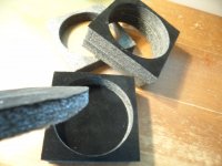
* My wife got a kinda fancy/delicate Snow Globe, for Christmas
...& it was suspended/packaged, in some 1/2" thick layers of Closed Cell Foam
They even "glued" a layer of black felt, to the foam, ta make it look all-fancy :sifone:
SAM_6600 (2).JPG
 

Functional Artist

Well-known member
Messages
5,350
Reaction score
2,841
Location
Toledo, Ohio
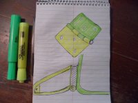
More drawin'

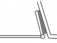
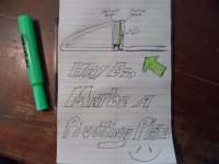
Ta illustrate the "hinge style" that I have in mind
...which is kinda like a door hinge

Which would be made of 1" OD steel tube (as the bushing holder)
...& (2) steel plates (as "pad" backing plates)
&
If the "backing plates" were welded
...to each side of the 1" OD tube
...they would be "spaced" ~1" apart
So,
It just seemed like a 1" thick "pad"
...would "fit" nicely, in between 'em
...& should compress "relatively" evenly :thumbsup:
SAM_6597 (1).JPG
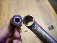
Here is an example of a DIY rubber bushing
...& 1" OD steel tube (bushing holder)
SAM_6418 (1).JPG
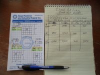
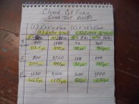
Also, "worked" on "refining" some of the "Crush Test" data

Since the Crush Tests were done with 2" x 2" x 1" samples
...& the samples consist of (4) 1" x 1" x 1" squares

I divided the results by (4)
...to convert the test data
...into psi readings :smartass:

* I used the same concept to convert the (2) layer test results
...but, probably should have divided by (8) o_O
...so, don't pay any attention to those readings :p
SAM_6595 (1).JPG
 
Top