fowler
New member
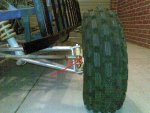
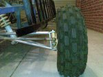
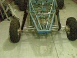
there doesnt appear to be too much wrong with the ackerman of that pic
the welding a screw thing will never break if it is welded properly
iv seen a welded 10mm bolt hold 1 tonne off the ground
u need to make the sindles double sheer
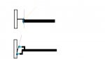
rose joints like above will work but u need two each sid and have them screw into the frame, this will help adjust the geometry.
u need new tie rods as the current ones are no good
u will need some ball joints and some tie rod (big long bolt)
lastly that red line is showing u the angle that your kingpin needs to be at
the top drawing shows the setup u have and the bottom show the setup u need
note how the whole setup is closer to the wheel some on it is sitting inside the wheel
take a look under your car that is what we are trying to recreate
the welding a screw thing will never break if it is welded properly
iv seen a welded 10mm bolt hold 1 tonne off the ground
u need to make the sindles double sheer
rose joints like above will work but u need two each sid and have them screw into the frame, this will help adjust the geometry.
u need new tie rods as the current ones are no good
u will need some ball joints and some tie rod (big long bolt)
lastly that red line is showing u the angle that your kingpin needs to be at
the top drawing shows the setup u have and the bottom show the setup u need
note how the whole setup is closer to the wheel some on it is sitting inside the wheel
take a look under your car that is what we are trying to recreate
Attachments
-
 steering.jpg17.7 KB · Views: 18

")