2S Keisler
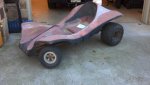
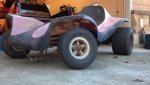
The Dune Cat
^^ On 'sid's project, please start an new thread 'sid. I want to keep this thread to the Dune Cat only.
Wow, I'd really like to see the +10 inch body and I would be very interested in one. Sorry this is my first post, I really did just stumble onto this forum. I've been looking for a cool mini Manx style glass body for a full suspension kart/buggy I designed with a 2 stroke shifter engine and Fox 2.0 shocks. It would have a cage and seat belt for safety but still be easy to get in and out of.
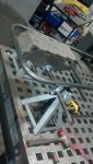
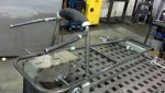
Shafi, that build table with the square holes looks very much like one in the Framecrafter's shop in Union, IL. Man I'd really like to have one of those for my shop.
Anyway, keep up the good work. I'm digging it. Talk soon, Travis

They're looking great,
but may I ask you something,
I am trying to make a fiberglass body myself
with all the materials (protobody, mold, actual body) I end up spending less than 500
(If I don't break anything in the process)
And that's calculated for making exactly ONE body.
Every other body would end up being around 150-200 max.
(all unpainted)
So I have the strong feeling I am missing something important in my plans.
Would you help me out and point me to what I may have missed to consider?
Thank you
'sid


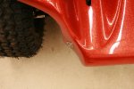
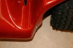
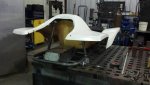
4. Nose mounting to frame - the original design is not symmetric at the mounting points and is easy to get out of alignment to the frame. This throws the pedal slots out of alignment too easily. So I am looking to make a fool proof way to mount the front of body.


")

