Boy Scout kart build - dubbed "The Hot Rod"

Status
Not open for further replies.

Bugzuki

New member
Messages
62
Reaction score
0
Location
Monroe, WA
My eye's are starting to hurt trying to find that low bar your talking about! It looks excellent, at this rate you will be driving the thing soon!!

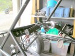
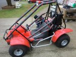
I am talking about the bar at the back of the upper control arm support bars. It is 1/4 inch low on the passengerside than on the drivers side. This causes the suspension on the passenger side to extend down at full droop than the drivers side. So the frame sits at an angle.

In this picture you can kind of tell that the passengers side is higher than the drivers side.


Thanks for the comments, but remember we started building this in November. I just did not know about this forum till last week, so I had to catch you up on the progress till now.


The wheel base is about 57" in the mockup. That might change according to the rear suspension design. The front width is currently 53" with not much weight on it. Rear is about 57 to 60" due to wider tires.
 

bighead

New member
Messages
4,022
Reaction score
52
Location
Pacific Northwest USA
I see you have not started mounting the sled engine. You have the whole sled right?

A good trick to be able to use the sleds belt and get the two clutches lined up right. Measure the distance from the center of both clutches. Then make a bar with the correct size hole in each end along with the sleds center to center distance. Hard to explain so here is a pic.

With this setup you can get the correct distance from the two clutches. Also give you the same size belt the sled ran. Also lines up the motor to be true as it can be. If bar does not slide easy on both shafts then it is not lined up right. Rock solid way to get it right and know what belt you need.

I can find the tread that these pics were taking from. Just let me know and I can dig it up. The pics are from a FL350 Honda Odyssey with a sled engine swap.


Also here is a good link on belt set up.

http://www.gates.com/brochure.cfm?brochure=1034&location_id=3850
 

Attachments

  • MVC-372F.jpg
    MVC-372F.jpg
    52.5 KB · Views: 275
  • MVC-377F.jpg
    MVC-377F.jpg
    57.1 KB · Views: 274

bighead

New member
Messages
4,022
Reaction score
52
Location
Pacific Northwest USA
Also you may want to check out this thread. Killdozer used the whole sleds frame and drive system on his kart. With this setup you do not have to worry about belt line up and engine mounting at all. It's already lined up. Also can use the sled brake for a parking brake. I really like he used the sleds tranny/reduction box. He also was able to use the sleds belt guards. He is able to gear it as well. I would put the brake on the axle though.

Being with suspension may be a problem with this mod. But just shooting some ideas at you.

Perhaps this will give you some ides.

http://www.diygokarts.com/vb/showthread.php?t=9565


Bluethunder3320

New member
Messages
5,677
Reaction score
37
isnt he using a quad engine?

anyways, that little kart looks like it flys bighead! you make the wings yet?
 

bighead

New member
Messages
4,022
Reaction score
52
Location
Pacific Northwest USA
isnt he using a quad engine?

anyways, that little kart looks like it flys bighead! you make the wings yet?

He is using a sled engine. Not useing the quad engine from what I am reading.

That is Killdozer kart. I love this kart. He took so much of the hard work out with his setup. I could only amagine how fast it is. He can also gear it to. Bad arse for a geared sled engine in a kart. I think is a 340 rotax. Are you kidding me?????
 

Bugzuki

New member
Messages
62
Reaction score
0
Location
Monroe, WA
Mounting Sled Engine

Bighead thanks for finding that bar idea, that is perfect. I will put the engine back in the sled and make that bar. This particular sled has a sheet aluminum chassis, so there is no frame to pull out. So, killdozer's method is not an option.

Thanks for the ideas.

Yes, I am using a 440cc 2 stroke air cooled sled engine w/ reverse. I don't think mine will be as fast as killdozer's

I picked up an 87 Ford Festiva steering rack today. It works the correct direction. I will see how it compares to the original plan.

We should be working on the cart some more tonight so, hopefully I will be able to get the guys to figure out mounting solutions for the steering column and rack, and seats. While I work on figuring out an engine mounting solution and rear suspension idea.
 

Bugzuki

New member
Messages
62
Reaction score
0
Location
Monroe, WA
i wonder if the front wheels ever touch the ground!

Seems like the back wheels would be too small (width and diameter) to lift the front. And the driver sits ahead of the rear wheels also. I would think the rear tires would just spin. It would be a great drifter.
 

Bugzuki

New member
Messages
62
Reaction score
0
Location
Monroe, WA
Is there are loss in power from modifying the exhaust of a 2 stroke like Killdozer did?

If not I will try to do something like that to get rid of the big U shaped pipe.
 

bighead

New member
Messages
4,022
Reaction score
52
Location
Pacific Northwest USA
Bighead thanks for finding that bar idea, that is perfect. I will put the engine back in the sled and make that bar. This particular sled has a sheet aluminum chassis, so there is no frame to pull out. So, killdozer's method is not an option.

Thanks for the ideas.

Yes, I am using a 440cc 2 stroke air cooled sled engine w/ reverse. I don't think mine will be as fast as killdozer's

I picked up an 87 Ford Festiva steering rack today. It works the correct direction. I will see how it compares to the original plan.

We should be working on the cart some more tonight so, hopefully I will be able to get the guys to figure out mounting solutions for the steering column and rack, and seats. While I work on figuring out an engine mounting solution and rear suspension idea.


Edit: I see your using a rack. Sorry.

The bar trick is really good. Lets you get the correct belt and everything. Takes all the guess work out. Just put your bar on and them fab the mounts. Good luck friend.

I would stay with the stock pipe if you can. Sometimes you can mod them to fit in and look good. I put a sled engine in an ody. This is what I did. I just moded the header pipe. My sleds pipe is older and big and ugly. But I got it to look okay by a simple mod. I used the sleds air box as well. Along with the tool boxes.
 

Attachments

  • PA260005.jpg
    PA260005.jpg
    99.7 KB · Views: 29
  • bell_crank.jpg
    bell_crank.jpg
    19.7 KB · Views: 31
  • CIMG1191.jpg
    CIMG1191.jpg
    73.5 KB · Views: 23
  • CIMG1193.jpg
    CIMG1193.jpg
    72.9 KB · Views: 19
  • CIMG3809.jpg
    CIMG3809.jpg
    107.5 KB · Views: 26
  • CIMG4171.jpg
    CIMG4171.jpg
    117.4 KB · Views: 29

Bugzuki

New member
Messages
62
Reaction score
0
Location
Monroe, WA
[/B]


Edit: I see your using a rack. Sorry.

The bar trick is really good. Lets you get the correct belt and everything. Takes all the guess work out. Just put your bar on and them fab the mounts. Good luck friend.

I would stay with the stock pipe if you can. Sometimes you can mod them to fit in and look good. I put a sled engine in an ody. This is what I did. I just moded the header pipe. My sleds pipe is older and big and ugly. But I got it to look okay by a simple mod. I used the sleds air box as well. Along with the tool boxes.

Thanks for the pictures. I do like how you modified the exhaust to work. My exhaust is similar, but have a much thighter U shape. I will post some pics when I can. I am thinking about swivelling the pipe vertical and then having the muffler above the engine sticking up in the air.
 

Rustydog2010

NZ Nutta :|
Messages
945
Reaction score
2
Location
New Zealand
If water is allowed to make it into the exhaust, make sure you have some small holes at the lowest point, so it doesn't rot out.

Jeremy.
 

Bugzuki

New member
Messages
62
Reaction score
0
Location
Monroe, WA
Finally an update on the progress. I have done some more work on the front. I have the steering rack mounted but have a bump steer issue with the right side.

I moved everything forward an inch to help correct the rubbing issue.

We have some progress on the seat mounting.

And I have been working on the rear end of the kart to figure out the mounting of the engine and drive system.

Here is another picture of the CAD design to illustrate where I am headed at this point in time.


I have also been working on the rear suspension as you can see from the picture. I have come up with an inexpensive way to make some bushing instead of using rod ends. The difficulty will be keeping tolerances close.

Here is the components I made:


So the pieces fit together like this:


Then, the final device looks like this:


This will be welded to the end of the control arms and go between the frame brackets. A 3/8th inch bolt goes through the middle.

:idea2: Hopefully we will be able to get some more of the bushings made tonight and some of the control arms built.
 

redsox985

Active member
Messages
4,092
Reaction score
12
Location
PA
That's a good idea. Are you using pre-bent C-brackets? They are very inconsistent. Ensure that the holes are all nearly perfect or else the swinging motion won't be smooth.
 

Bugzuki

New member
Messages
62
Reaction score
0
Location
Monroe, WA
That's a good idea. Are you using pre-bent C-brackets? They are very inconsistent. Ensure that the holes are all nearly perfect or else the swinging motion won't be smooth.

Thanks, I think it was a pretty good idea too (if I do say so myself). Pre-bent C-brackets :huh: We are making everything. I am trying to get the boys to understand the need to actually cut things to the correct length, but they just don't get the need. 12 7/8th is close enough to 13 isn't it.

Hopefully we can use jigs and get the control arms mostly the same and straight. It would be nice if the back drove straight, but a little dog walk is not a show stopper.

I got a couple pictures of the boys cutting and turning tonight. I try and get them up soon.

this build is looking great ! can't wait to see it finished

Thanks for the comment.
 

Risen

New member
Messages
27
Reaction score
0
Location
Phx. az.
Finally an update on the progress. I have done some more work on the front. I have the steering rack mounted but have a bump steer issue with the right side.

I moved everything forward an inch to help correct the rubbing issue.

We have some progress on the seat mounting.

And I have been working on the rear end of the kart to figure out the mounting of the engine and drive system.

Here is another picture of the CAD design to illustrate where I am headed at this point in time.


I have also been working on the rear suspension as you can see from the picture. I have come up with an inexpensive way to make some bushing instead of using rod ends. The difficulty will be keeping tolerances close.

Here is the components I made:


So the pieces fit together like this:


Then, the final device looks like this:


This will be welded to the end of the control arms and go between the frame brackets. A 3/8th inch bolt goes through the middle.

:idea2: Hopefully we will be able to get some more of the bushings made tonight and some of the control arms built.

Good to see that you are making some progress. One thing that I do see with the bushings that you will be using, the big bushing tube that you are going with has a thin wall, you want to go with a thicker wall tube for your bushings. The thinner wall will cut into your bushings faster(think of it as a cookie cutter situation) where if you where to go with a thicker wall you add more surface area for the outer sleeve to ride on the rubber bushing rather then cut into it.

Go with a thicker wall outer tube and then turn down the rubber bushings on a lathe to a clearance fit you can still use the same rubber bushings and inner sleeve and bolt.
 

Bugzuki

New member
Messages
62
Reaction score
0
Location
Monroe, WA
Good to see that you are making some progress. One thing that I do see with the bushings that you will be using, the big bushing tube that you are going with has a thin wall, you want to go with a thicker wall tube for your bushings. The thinner wall will cut into your bushings faster(think of it as a cookie cutter situation) where if you where to go with a thicker wall you add more surface area for the outer sleeve to ride on the rubber bushing rather then cut into it.

Go with a thicker wall outer tube and then turn down the rubber bushings on a lathe to a clearance fit you can still use the same rubber bushings and inner sleeve and bolt.

I can see how that could be an issue. I don't see how I would turn the bushings down in the lathe. So I would have to remake them, not expensive just time consuming. The bushings are made out of UHMW-PE which is a somewhat hard plastic, not rubber. It is also self lubricating. The bushings mostly swivel on the inner tube as opposed to the outer tube. I have also already started welding the control arms together.

I think at this point I will see how they perform and revise the design as needed.

Thanks for the input.
 

Risen

New member
Messages
27
Reaction score
0
Location
Phx. az.
I can see how that could be an issue. I don't see how I would turn the bushings down in the lathe. So I would have to remake them, not expensive just time consuming. The bushings are made out of UHMW-PE which is a somewhat hard plastic, not rubber. It is also self lubricating. The bushings mostly swivel on the inner tube as opposed to the outer tube. I have also already started welding the control arms together.

I think at this point I will see how they perform and revise the design as needed.

Thanks for the input.

If the bushings are a hard enough plastic you should still be able to turn them on the lathe.I have been involved with building sand cars and pre-runners for the past ten years and that is what we found to work the best on cutting down on having to replace the bushings as often.It is also important to make sure the that the small inner sleeves or made correctly by making sure that they are just long enough to fit in between the tabs so that when you go to tighten the bolt the tabs compress flush on the inner metal sleeve and the outer face of the bushing at the same time. The idea is to have the metal tabs compress on the metal sleeves, if the sleeves are to short even by just a little bit the tabs will compress on the bushing first and for sure cause pre-mature bushing failure.

Use a caliper to measure the inside distance between the tab then use a lathe to trim the sleeve to that measurement.
 

Badot

New member
Messages
677
Reaction score
2
UHMW is an excellent material for bushings. Yes, you can turn it on a lathe, but it's not the easiest to machine. They make bulletproof vests out of this stuff (Dyneema and Spectra) as well as use it for joint replacements.
 
Status
Not open for further replies.
Top