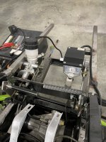
80v AWD Performance Build

Piratelegs

New member
Messages
2
Reaction score
0
I’m interesting in building a similar kart. I don’t see anyone else asking here, but what brand are these components? Where can I buy them? The front and rear suspension looks good and the motor too
 

Mr.Mediocre

Member
Messages
36
Reaction score
42
Location
North Carolina
I’m interesting in building a similar kart. I don’t see anyone else asking here, but what brand are these components? Where can I buy them? The front and rear suspension looks good and the motor too
Hey Piratelegs!
So the front and rear suspension geometry was cut off of a Greenworks Commercial UTV.

-The green coilovers were by a company called SAIR. Seems to be some Chinese company so nothing special.

-The current shocks are Monroe Max-Air, air shocks. These are probably not the best choice but I needed something cheap and to get me started.

-The controller is a Curtis 1234SE AC motor controller. This has been my biggest hurdle, since it was pre-programmed to the original UTV I’ve had a heck of a time trying to track down what parts of the wiring go to what was previously programmed to be required.

-The motor was the OEM 48V motor which is made by their company called Globe.

-The battery pack is from the UTV and has built in BMS but similar to used EV batteries, I think salvaging one is really the only way to get one.

So besides the shocks and controller not much can be found for purchase straight up. I will say that I’m thinking about abandoning the controller for something more plug and play. Maybe from Electro & Company. If someone knew more about controllers I’m sure they could figure it out but I don’t have that knowledge. 😔
 

AndyW

New member
Messages
19
Reaction score
14
I’m interesting in building a similar kart. I don’t see anyone else asking here, but what brand are these components? Where can I buy them? The front and rear suspension looks good and the motor too
These items I just put up for sale might be perfect for a large kart project. That is what I purchased them for. Take a look and let me know if you have any questions. https://www.diygokarts.com/community/threads/motenergy-me1907-bldc-kelly-motor-controller.47858/
 

Mr.Mediocre

Member
Messages
36
Reaction score
42
Location
North Carolina
...[deep breathes]... Okay, over the last month I've had the harness inside on my dining room table, on the floor of the garage, and now strung back into the kart. I was able to find a diagram from the manufacturer that white-labeled the UTV for Greenworks and it seems to match pretty closely. I was able to confirm connections and what wires from the relay box go where.

I was able to get 12V stuff powered up and the gauge cluster sweeps on and has power, along with the toggle switches light up.

The next step was to figure out the high-voltage stuff. It was super confusing because it felt like the diagram had several things connected to the battery positive before the contactor, along with battery negative at the controller. It felt like those were mixed with 12V but I was able to confirm that not the case. Obviously the positive isn't, the negative ground is however.


@Functional Artist I know you "didn't recommend" to try battery voltage to the KSI port 1. This current setup does in fact do that and I was able to run through the system making sure I knew where that voltage was going since the KSI wire is pigtailed into several other Red wires running through the harness. I also confirmed grounds throughout the system were good.

My current state:
The key turns on and the main contactor closes and the controller gets battery voltage, the toggle switches get power to their LEDs (through the DC-DC converter, and the dash swept on and turned off once and didn't do it again.

@Functional Artist I know you "didn't recommend" to try battery voltage to the KSI port 1. This current setup does in fact do that and I was able to run through the system making sure I knew where that voltage was going since the KSI wire is pigtailed into several other Red wires running through the harness. I also confirmed grounds throughout the system were good.

When I turn the key on to start, the controller gives me 3 errors:
- Error 31: Main coil open or short (Pin 6) - This pin is one of the 2 wires that run to the contactor to close it. I checked and confirmed that this wire isn't shorting to the second wire, and I checked the tabs on the contactor as well. So I have no idea especially since the contactor does actually close as it should.
- Error 55: OEM code, BMS PDO Fault. Says that the The service manual say (Time between CAN PDO messages (between controller and BMS) received exceeded the PDO Timeout Period. Check the communication wires from BMS.)
- Error 56: OEM code, Battery cell voltage is low. This one stinks because I have a charger for the battery but it won't charge. I believe I'm missing an onboard charger piece of some sort.

So once I get my new multi-meter in since mine broke last night, I plan to double check the CAN wires from the battery, try to see why the pin 6 wire is shorted or open, and then take my battery pack out and try to setup my smaller removable battery pack to test. :rolleyes:
 

Mr.Mediocre

Member
Messages
36
Reaction score
42
Location
North Carolina
Update:
I've tried to go through everything over and over again. After zapping out my 4wd actuator and my gauge cluster I was pretty frustrated and just over the whole thing. After I few days of to cool down I was able to find some pep to try and figure this thing out.

- I went through and made sure I wasn't missing any grounds, and the whole system is grounded to the controller/pack (-)
- I tried to isolate why some things were 12V and some were showing the pack voltage (77.5V). And when I say somethings, I mean wires that were leading to a dash switch! Someone else said that seems wrong and unsafe and I felt the same way.
- Tonight I separated the KSI wire that leads to pin 1 from the other Red (+) wires it was pigtailed into. That pigtail led to the fuse box, DC/DC converter and up to switches for some reason.

After doing all of that I was able to isolate the fault 31 code related to Pin 6. It was shorted out inside the controller to Pin 7 which I believe is a ground. So I swapped over my extra controller and tested that. Now I don't have fault code 31!

The next few things I need to figure out are:
- Fault Code 55 - PDO Timeout (BMS to Controller CAN timeout)
- What are the F/N/R & Mode Switches supposed to look like.

- The service manual shows:
Forward: Black & Yellow/White
Reverse: Black & Yellow/Green.

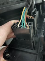
But when I had access to one of the UTVs this came from I took pictures of the back of the switches and they have a Blue/Green wire instead of the Black. To me it looks like Black & Red/Brown provide power for LEDs on the switch especially since every switch has a Black & Red/Brown wire.

I'm assuming Green/Blue is ground and White/Yellow & Green/Yellow are (+). A quick test tonight seems like that makes sense. But I think I have polarities reverse on something.

IMG_4178.jpg
 

Mr.Mediocre

Member
Messages
36
Reaction score
42
Location
North Carolina
Big Update! Holy moly do I have a big update!

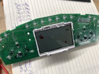
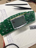
I pulled the gauges of the kart and opened them up... You can see where the trace pretty much exploded inside from the HV feeding into the gauges.

IMG_6538.JPG

I cleaned it up and soldered a wire in the bridge the gap. Tested continuity and put it back together after I confirmed 12V lit up the display.

IMG_6540.JPG

After getting the gauges fixed, I want to test to see if the actual gauge motors worked still and if anything else was blown. From the looks of it I didn't think so. Before I plugged it up and tested, I ran though my drive and mode switches and the gauge harness again to confirm my new separation of HV and LV was still good and it was.

Next step, plug it all up and test it out. Wouldn't you know it, the gauges swept on and lit up. After a few more minutes of trying to see which 12V wires needed power I got the drive and mode switches to register on the dash too! That meant the controller was seeing the switches change and relaying that over to the display. I just needed to figure out which wire was the parking brake and why the light was on.

Oh did I mention, I got it running?! I can't tell you how refreshing that was. I figured out the wire for parking brake and when the light went off and I put it in forward, the freaking wheels started spinning!


Mr.Mediocre

Member
Messages
36
Reaction score
42
Location
North Carolina
I felt like getting the wheels to spin was such an emotional victory for me that I couldn't touch the kart for about a week or so. :ROFLMAO: I needed time to come down before I accidentally messed something up.

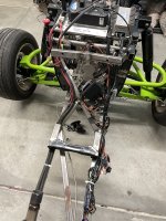
I tried to confirm what wires I had connected to different spots and clean it all up. did some electrical tape and zip-tie work and then tested it again. Everything still worked as before so that was great! Fuse box and relay mounted with some quick and dirty wire management.

IMG_6764.JPG

At this point I knew I wanted to sit in it and drive it but really wanted to make sure I slowed down to make sure a didn't screw anything up by forgetting to tie something down or whatever. I was sure the condition of the gear oil so I changed that out too.

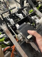
Next I needed brake lines and accelerator pedal linkage. I bought some banjo bolts and a used steel-braided brake line from the local race shop. and then started to test my accelerator pedal position and linkage.

IMG_6612.JPGIMG_6765.JPG
Once I got that all setup I powered it up and tested that as well.

That was it... I was now ready to bleed the brakes and jump in. I knew my dad would be in town this weekend so I waited to have an extra hand with the brakes. After three times around all four corners to make sure we were good it was time for a test drive!

I took it for a few back and forth runs as my wife and daughter sat in the driveway watch and then let my dad jump in so I could see what it looked like!

:auto:

It's not fast, and its not super pretty but it works. My year+ long adventure to a weird proof of concept I had well before that!

Next steps,
- Verify that the left rear wheel is in fact bent and figure out what wheels and tires should go on it next.
- Check to see why front right caliber has a pulse to it. (probably warped/bent rotor)
- Re-bleed the brakes
- Replace the actuator motor for the front differential that got burnt out from the 72V.
- Find a shop to bend me some tubing so I can add side rails that connect front to back on the upper side.
- Mount gauges
- Properly mount the battery
- properly mount the controller and dc-dc converter
- Find a shop that has a Curtis programmer and unleash more power to this thing!
 

Mr.Mediocre

Member
Messages
36
Reaction score
42
Location
North Carolina
Happy Sunday everyone.
I am writing this last update to close out the project.

Unfortunately, I've had some setbacks with working on the project and the biggest one is that I found metal shavings in both my motor oil and transmission fluid when working on my regular car. Which means that there is some money to be spent in the next few months. In order to prepare for the repair or replacement of both an engine/transmission or selling my car at a loss to find a new one I will be selling off this project. I will be posting pictures and components on a separate post.

I want to thank all of you for the help along the way, all of the troubleshooting and guidance. I hope to jump into a smaller and easier project later when everything settles down but until... Thank you all.

Keep an eye out for a sale post later today when I return home and can post. ❤️
 
Top