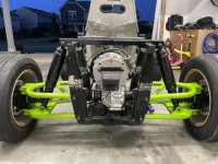
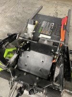
80v AWD Performance Build

Mr.Mediocre

Member
Messages
36
Reaction score
42
Location
North Carolina
I'm not an EV expert, but I do have some electronics knowledge and did research building a homemade EV for commuting. It didn't pan out dollar wise (a ****box gas commuter is still cheaper to operate than buying batteries), so I didn't build it.
Yeah, when I got the suspension and all, I thought man I should just throw this into a Mini K Truck. It’s about the same size and weight of a UTV. But cost stopped me!

Is that controller what comes on these UTV things you're getting parts from? Is it the same motor from the same UTV? It seems like a very nice sophisticated controller...
Yeah this is all a matched set, from different UTVs but same model. I guess I never thought about the idea that they could be running 82v (72.6 nominal) to the controller but the controller is just sending 48v out to the motor. That could explain why they claim to get 70 miles of run time in the lowest setting with the bigger 13kW battery pack or whatever comes with it. I’ll be interested to get it all plugged up and see what readings I get.

The 82V rating must be due to different batter chemistry?
I thought I saw Lithium-Phosphate somewhere but I just double checked and they are all Lithium-ion. And yeah they advertise max voltage not nominal, so 60V is 56V the 82V is 73V weirdly enough. And The 80V batteries don’t say their nominal voltage. When I set out into this project, the idea was to have removable batteries that could be easily swapped and also charge back up in 90 minutes. I have no idea how long the slightly bigger 3kW pack would take with the heavy duty wall charger either.

So, everything in those pictures looks like awesome stuff to me :). It would be fun to get my hands on one of those motors, and any of the suspension parts.
Motors seem to be lying around more than anything so I can definitely keep an eye out. As for the suspension, I think there are two units with coil overs on them still. Cutting the full sections probably wont happen now that they are in there at super sketchy angles, mine was in the bottom with nothing around it when I went in. I’ll keep an eye out so some goodies.

@MTScott Thank you for the brain dump, I’ve been fascinated in all of this tech for awhile now and have struggled to find a one stop source for good breakdowns and explanations so I feel like I’m just piecing it together.

I think I ready somewhere that the phase wires to the motor should be equal length, Anyone know how important that is? I had some scrap EV Cable I used to make these but as soon as I finished I thought… Shoot I think those are supposed to be the same length.
021E23F5-AFB9-4825-8A68-E5DCEDF3D413.jpeg
 

Mr.Mediocre

Member
Messages
36
Reaction score
42
Location
North Carolina
Okay so I can't help myself. I found specs on both of the greenworks 80v and 82v batteries. They are both nominally 72V packs, indicating they are 20cell packs, that will really both likely peak at 82V (if the charger will take them there). I'm guessing the 80 vs 82V rating is to make it clear which pack is for the commercial product line, and which is for common grade products. So, the only thing I'd base my choices on is Ah rating, both of which have varying options. Now that I've looked at their stuff deeper, it seems like you're using a 6 bay receptacle device that might come on one of their lawn mowers to create the "pack" on the cart.
I just saw this reply too. Yea you’re right I have both a 60V and 80V 6 port battery box from the consumer riding mowers. And recently I got the 82v battery box that is all built in one as well, which came from a commercial unit. Interesting that the 80v & 82v would both Be the same nominal voltage, I’m guessing the BMI is what allows it to charge up to 82.
 

MTScott

Active member
Messages
146
Reaction score
128
Location
Montana
I just saw this reply too. Yea you’re right I have both a 60V and 80V 6 port battery box from the consumer riding mowers. And recently I got the 82v battery box that is all built in one as well, which came from a commercial unit. Interesting that the 80v & 82v would both Be the same nominal voltage, I’m guessing the BMI is what allows it to charge up to 82.

Somewhere I found the specs for the 80V, and they reported as 72V nominal, and the math makes sense.

I'd be surprised if they actually charge to different max voltages.... 82V brings the cells to 4.1V, which is a safe limit, and I think fairly standard. L-ion cells "can" go to 4.2V per cell. So, 82V is an appropriate max charge. If the "80V" packs truly only charged to 80V, it would be kind of a shame, but who knows, maybe there is a good explanation.

I like how clean all this stuff looks with the 6 port battery boxes and the removable packs.... it looks a bit pricey for a guy that doesn't have an "in" though. Swapping in pre-charged extras will be a breeze. Literally plug-n-play, and the charging solution is already all figured out.

Alright, I've run my mouth enough in your build thread.

Good luck!
 

Mr.Mediocre

Member
Messages
36
Reaction score
42
Location
North Carolina
UPDATE:
So progress has been slower than I wanted, I lost my job at the end of February and didn't touch the kart for the 2 months I was searching for a new gig. Lucky I found the motivation to get back in the garage and try to make up for some of the lost progress.

I locked in the steering column location and mounting. I was able to find an adjustable bracket so I can raise and lower the steering wheel if need be.

IMG_5035.JPG

I finalized the mounting bracket for the controller and the DC-to-DC Converter. That got a little too close to the seat and I was also thinking I needed to sit upright just a bit more so I re-fabbed the rear seat bracket and finished the bottom bracket as well.

IMG_5033.JPGIMG_5031.JPG

The most recent piece I did was make the brake and accelerator pedals. I didn't like the big bulky pedals that I had so I made some that drew inspiration from go kart pedals.

IMG_5029.JPG

The next thing I am hoping to do is buy the shocks for it. I realized that I couldn't have it sit as low as I wanted since there isn't any camber adjustments on the suspension so I'll have to let it sit a bit higher. This should work out for better off-road ground clearance.

IMG_4897.JPGIMG_5028.JPG

NEXT STEPS:
I'm hoping to get shocks ordered this week, that way I'll officially have a rolling chassis. I will finish fabricating the brake booster mount and try to lock in the pedals finally.

I've tried to test run it with no luck. I am missing a few parts to the in the wiring harness to get it going. Apparently I need a main relay and without it, the controller doesn't recognize the key being turned on and let power pass through to the harness. Based on the wiring diagram it looks like I'm missing the a CAN converter too. Those will be the big electrical troubleshooting.

Thanks for checking in and hope you enjoy the updates!
 

BaconBitRacing

Well-known member
Messages
2,180
Reaction score
1,296
Location
N.C.
Sorry about your job, seems to be happening a lot as of late. This is quite the cool project, I'm excited to see it finish. What wheels are one there?
 

Mr.Mediocre

Member
Messages
36
Reaction score
42
Location
North Carolina
Sorry about your job, seems to be happening a lot as of late. This is quite the cool project, I'm excited to see it finish. What wheels are one there?
Thanks BaconBit, I appreciate that. It was definitely unexpected and frustrating for sure. It's crazy how much I hear it happening too!

The wheels are from an older Mazda Miata. Since the hubs are from a UTV they have a harder to find bolt pattern so I opted for adapters and $50 craigslist wheels rather than the the pricier UTV wheels.
 

BaconBitRacing

Well-known member
Messages
2,180
Reaction score
1,296
Location
N.C.
Thanks BaconBit, I appreciate that. It was definitely unexpected and frustrating for sure. It's crazy how much I hear it happening too!

The wheels are from an older Mazda Miata. Since the hubs are from a UTV they have a harder to find bolt pattern so I opted for adapters and $50 craigslist wheels rather than the the pricier UTV wheels.
I guessed right! Yay! Do I get a prize? I hope you can find a new job, around here (I live near a city) there's lots of entry level jobs and no workers. I guess it's different further away from cities where the job market is more dependent on one or two businesses.
 

JessieJim1

New member
Messages
8
Reaction score
5
UPDATE:
So progress has been slower than I wanted, I lost my job at the end of February and didn't touch the kart for the 2 months I was searching for a new gig. Lucky I found the motivation to get back in the garage and try to make up for some of the lost progress.

I locked in the steering column location and mounting. I was able to find an adjustable bracket so I can raise and lower the steering wheel if need be.

View attachment 138028

I finalized the mounting bracket for the controller and the DC-to-DC Converter. That got a little too close to the seat and I was also thinking I needed to sit upright just a bit more so I re-fabbed the rear seat bracket and finished the bottom bracket as well.

View attachment 138029View attachment 138030

The most recent piece I did was make the brake and accelerator pedals. I didn't like the big bulky pedals that I had so I made some that drew inspiration from go kart pedals.

View attachment 138031

The next thing I am hoping to do is buy the shocks for it. I realized that I couldn't have it sit as low as I wanted since there isn't any camber adjustments on the suspension so I'll have to let it sit a bit higher. This should work out for better off-road ground clearance.

View attachment 138032View attachment 138033

NEXT STEPS:
I'm hoping to get shocks ordered this week, that way I'll officially have a rolling chassis. I will finish fabricating the brake booster mount and try to lock in the pedals finally.

I've tried to test run it with no luck. I am missing a few parts to the in the wiring harness to get it going. Apparently I need a main relay and without it, the controller doesn't recognize the key being turned on and let power pass through to the harness. Based on the wiring diagram it looks like I'm missing the a CAN converter too. Those will be the big electrical troubleshooting.

Thanks for checking in and hope you enjoy the updates!
it's great, well done!
 

Mr.Mediocre

Member
Messages
36
Reaction score
42
Location
North Carolina
Waiting for updates for sure
How funny, I was out there earlier and hit a road block and decided to come in to give an update and just saw your message!

So this is the pinnacle of budget build, everything has been as cheap as I can find it or reused in some way. So with that being said, I finally ordered shocks. They are supposed to arrive tomorrow and Sunday. I went with some used Monroe air struts. I figured they are designed for up to 1200lbs. and with me in it the kart is only 700-800lbs. At-least it should let me get the thing rolling around.

After tonight I feel like I need a win so I'm hoping those work out and over the extended weekend I can get it rolling.

Today I got the relay box, which they call the (relay combination - #21) It's not officially from GW since its really hard to find one of their dealers but it is from HiSun which the frame and a lot of the UTV was made up of, it also has the exact same plugs.
IMG_5703.JPGScreen Shot 2023-05-26 at 9.17.00 PM.png
Unfortunately I am still not getting power to the dash cluster and the main contractor doesn't close to pass power through to the controller. When looking through some of the diagrams it still looks like I am missing what they call the (72 Main Relay - #20) I have what they call a (72V Open Relay - #25) but I guess I still have more to complete some of the circuit. And I think that's what is tough, I feel like I have enough to make it work if I went in and bypassed the program that's in there, I know other people get motors running with a lot less.

Also, nowhere in the parts list do they have what I've been calling the CAN converter, but in on page in one PDF it has one listed with other components so who knows if I get this Main Relay if that will even be enough.

Definitely feeling beaten up by it tonight especially knowing that August is coming up fast which means it will be a year from when I started and it's killing me on how slow it's been.

Thanks for asking about it!
 

Mr.Mediocre

Member
Messages
36
Reaction score
42
Location
North Carolina
Have a small win for today. I got the front shocks in and installed. With the help of some WD40, a razor blade, I was able to trim and squeeze the slightly oversized rubber bushings into the shock supports and bolt it up! and I walked away with only one skinned knuckle.

IMG_5709.JPG

I was also able to get the airlines hooked up and tested. with me standing on it hopping up and down it did great and I was able to watch the pressure readout on my air pump and saw that it didn't exceed the max pressure too.
 

Mr.Mediocre

Member
Messages
36
Reaction score
42
Location
North Carolina
Rear air shocks came in and after trimming the bushings I was able to get those installed too. Unfortunately, the schrader valve that shipped with them was cracked so I had to order a new one and it finally came in while I was away for work so I finally got everything on and aired up.

For the first time since I started the kart it stands on its own, I officially have a role chassis! I should probably get the anti-sway bar back on the front too. Question... Should I put each air shock air line on its own valve or keep the front two connected and the rear two connected?

IMG_5777.JPG

IMG_5857.JPG

I was also able to to make some progress on the pedal assembly.
IMG_5775.JPG

I was able to use some of the frame tube that I trimmed off to make a spacer for the brake booster.
IMG_5776.JPG

I'm currently working on linking the accelerator pedal to the throttle pedal box. I need to find an adapter to fit on the spline and reach to the linkage.
IMG_5876.JPG

I also found a Main Relay that looks to use the same connector that is on my wiring harness and that should be here by the end of the week. So I am hoping that with the main relay I will actually get power to the controller and dash. 🤞

Small progress but feeling hopeful!
 

Bansil

Painter of gnomes....
Messages
1,360
Reaction score
914
Location
Mnts of the farthest NE TN you can go
If you connect side to side, the air will be forced to the other side to try to push it down when opposite side goes up. may handle weird on a kart, slow offroad I have seen it work, but individual would be simple at 1st then you can experiment?
 

Mr.Mediocre

Member
Messages
36
Reaction score
42
Location
North Carolina
If you connect side to side, the air will be forced to the other side to try to push it down when opposite side goes up. may handle weird on a kart, slow offroad I have seen it work, but individual would be simple at 1st then you can experiment?
Yeah, that was what I thought. I think it would be subtle since the hoses are so small but it may almost add more roll into a turn which isn't what I'd want.
 

Mr.Mediocre

Member
Messages
36
Reaction score
42
Location
North Carolina
I was able to fab up some simple brackets to mount the dash cluster, so check that off the list.

IMG_5879.JPGIMG_5880.JPG

Also, revisited the pedal assembly placement. You can see a tab sticking out on the left side of the pedals, there is one on each side that I plan on cutting off and flipping to hang underneath of the tube. That will give me a spot to mount.

IMG_5881.JPG
 

Mr.Mediocre

Member
Messages
36
Reaction score
42
Location
North Carolina
Okay, I need some help/advice troubleshooting this...

I got what I though might be one of the final pieces to my electrical puzzle in and still nothing. I turn the key and inside the battery box you can hear a click and I confirmed that voltage is coming out with my meter.

But something else in the wiring harness is not seeing the key turn on because the contactor doesn't click on.

If I connect a separate battery to the contactor it will click on and I can confirm that voltage passes through that and hits the B+ and B- terminals of the controller.

But nothing else will happen, I don't see the two LEDs (used for error codes) on the controller light up and the dash doesn't get power either.

I thought I had all of my relays and fuses covered, but it seems like I'm missing one. The wiring harness has a few connections that I don't have connected to anything but I can't figure out what else I could be missing from the owners/service manual that I have on the unit it came out of.

The Curtis Controller manual has a nice wiring diagram but I'm not sure if that would give me the information I need to see if I'm missing something.

Is there a way that I could test the connectors I have with my multimeter to get any clues on if I'm missing a relay or is one isn't working?

Based on the Curtis Controller manual
- Pin 1 is the KSI (Keyswitch input. Provides logic power for the controller and power for the coil drivers)
- Pin 13 is Coil Return (This is the coil return pin (at B+ potential) for all the contactor coils)
- How would I check these two to see if they are getting the right signal? They seem to be the culprits that would prevent the contacor and controller from getting power.


Thank you in advanced for any help!
 

Mr.Mediocre

Member
Messages
36
Reaction score
42
Location
North Carolina
Simplify things ;)

Check & verify each circuit individually :thumbsup:

Post the wiring diagram
...& any other pertinent info
...& we'll try-n-help, figure it out :cheers2:

Thank you @Functional Artist unfortunately the wiring diagram that is in my service manual pdf is the lowest quality I've ever seen. I'm trying to reach out to my contacts to see if they have an updated version that is more useful!

Here is the diagram... Good luck making anything of it though.
CU800_Motor&Controller Diagram.png

Here is the diagram for the Curtis Controller and the typical Pin assignments.

Curtis_1234E_Controller_Diagram.png

Not much of the wiring harness is labeled but there are a few spots that do have some information.

The battery box has two connectors coming out of it.
- First Plug (ACC, OFF, START): This is where I have my keyswitch connected and when I turn the key and hold it, I hear the battery's internals click.

- Second Plug (C12V-, C12V+, TCANL, TCANH, D12V-, C12V+, CANL, CANH): This has an 8 pin connector and matches up with an 8 pin connector on the main harness.

With this I was able to perform a continuity test at the controller side and confirmed that the (CANL, CANH) Pins do in fact match with the Curtis Diagram for Pins 23 & 35. (TCANL, TCANH) Do not go to the controller where the Curtis Diagram says they should (Pins 21& 34), I did not do a continuity test on the other pins to see yet. (NOTE: Pins 21 & 34 are not pinned at all in the controller side connector)

Because I have no idea what those other D12V, and C12V would be for I did not try to trace those either. I did however test to see if any of those pins would connect to Pin 1 (KeySwitch) and none of them do. This is why I am wondering if my key needs to be connected somewhere else in the harness to tell the controller it is on. I did a continuity test on Pin 1 and went around to a few open connectors to see if anything would buzz and I did get 2 or 3 other open connectors that had continuity with Pin 1. Not sure what to do with that information.

At this point I am thinking is a good time to cut the harness open and use that to help trace wires since I know I'll want to thin it out eventually. Maybe before I do that I will take a look at what Pins are being used on my main controller harness and start diagraming that out with wire color too.

Thanks again!
 

Functional Artist

Well-known member
Messages
4,409
Reaction score
1,691
Location
Toledo, Ohio
Well, this is a big "gray area" :unsure:
Today I got the relay box, which they call the (relay combination - #21) It's not officially from GW since its really hard to find one of their dealers but it is from HiSun which the frame and a lot of the UTV was made up of, it also has the exact same plugs.
...&
I hear the battery's internals click.
This could be the BMS turning on

I'm not advising it
...but, a "test" would be to simply bypass that harness (for a minute) ;)

Looking at the (Figure 3) diagram (posted above), it looks like applying power (pack voltage) to the KSI (J1-1) should "manually" turn it on
...& to the contactor's coil (also, should "manually" turn it on)
...& (maybe) to Forward (J1-22) (to indicate to the controller, that you want the motor, to go forward)

* Make sure the battery, motor & throttle are connected to the controller properly :cheers2:
 

Mr.Mediocre

Member
Messages
36
Reaction score
42
Location
North Carolina
Well, this is a big "gray area" :unsure:

...&

This could be the BMS turning on

I'm not advising it
...but, a "test" would be to simply bypass that harness (for a minute) ;)
Yeah I assumed it was the internal BMS clicking in the battery.

haha I may attempt a quick workaround, but before that I want to take a closer look at where everything is going. I spent the last 2 hours cutting away all of the electrical tape and wire loom on most of the harness.

It revealed that my biggest problem is there is an open circuit. The two wires that lead to the contactor went all the way up the harness and then split with each wire going into about 4 different connectors all wired in a series like configuration. One of those connectors was an 72V open relay but not sure what all the others are for. Once I traced that series of connectors I noticed that to complete the circuit the last two wires went back towards the controller pin out and went to Pins 13 and I believe 7. Which would make sense, KSI Coil Return and Ground.

Next I want to trace down a few more connections and I think if I feel good about some of those I will try to close that circuit and simplify it.
 
Top