48v 1000 go kart upgrade to 1800w

itsid

Moderator
Staff member
Messages
11,563
Reaction score
248
Location
Ruhrpott [Germany]
hehe.. I hate touchpads so I always carry a mouse with my laptop and use that instead.

And if your touchpad's no longer working,
chances are you can get a few extra miles
if you get yourself a mouse and use that instead for now :D

just saying

'sid

PS If you still want to see if you can finish this for her birthday,
we could skip the testing with the arduino entirely and test everything else instead..
what do you think? shall we try?
 

Tony86

New member
Messages
96
Reaction score
0
Location
London
Yeah that would be awesome :) I get the mouse prob thursday its not the end of the world if she don't ... bin long enough :roflol:but can see the end is near:thumbsup::cheers2:
Thankyoun
Tony
 

itsid

Moderator
Staff member
Messages
11,563
Reaction score
248
Location
Ruhrpott [Germany]
WEll then let's move the motor test aside and proceed.

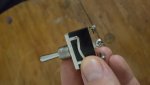
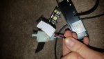
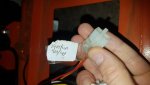
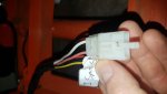
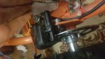
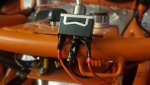
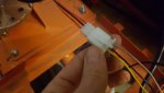
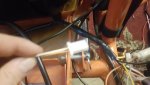
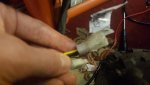
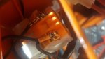
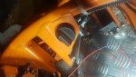
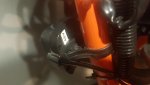
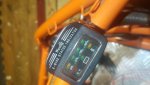
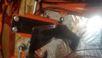
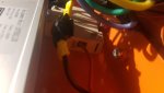
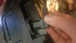
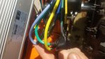
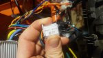
Please take good pics of all the switches, (connection side is most important)
and the throttle.

I'll then tell you how to safely test those with a multimeter and we start to connect all up.
either it works,
or it doesn't.. if it doesn't, chances are it's the motor's fault then.

'sid
 

Tony86

New member
Messages
96
Reaction score
0
Location
London
Throttle
Brake
3 speed
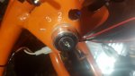
On/off key
Indicator
Forward and reverse to be fitted
Thankyou tony
 

Attachments

  • 20200304_035254.jpg
    20200304_035254.jpg
    100.4 KB · Views: 5
  • 20200304_035420.jpg
    20200304_035420.jpg
    178.5 KB · Views: 5
  • 20200304_035512.jpg
    20200304_035512.jpg
    146.9 KB · Views: 5
  • 20200304_035615.jpg
    20200304_035615.jpg
    124.2 KB · Views: 5
  • 20200304_035642.jpg
    20200304_035642.jpg
    137.6 KB · Views: 3
  • 20200304_035716.jpg
    20200304_035716.jpg
    140.4 KB · Views: 3

itsid

Moderator
Staff member
Messages
11,563
Reaction score
248
Location
Ruhrpott [Germany]
Great,

First Task:

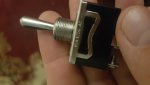
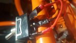
now take the switch from pic one (that's the forward reverse switch you got, right?)

leave the lever in the center "OFF" position.
Set the multimeter to Continuity test
(it's the orange setting on the multimeterdial next to the "10A" label)

touch the probes to each other (it should beep)
and if it does, touch the center terminal screw with one probe
and the metal part of the case with the other
if it beeps we need to insulate that switch against the kart frame somehow.
Let me know if it does!​

Second Task:
Take the wire coming from the brake pedal..
leave the multimeter at the continuity setting.
touch the two wires in the connector and tell me if it beeps
when the brake pedal is depressed or relaxed.​

Third Task:
This a tiny bit more difficult I'm afraid.
we need power on the throttle pedal...

So remove All but the red and black wires from your Arduino;
Use a blue wire an put it to the second pin next to the red wire (it says GND)

and attach the red and black wire from the arduino to the black
and red wires on the throttle pedal (clolor matching)

Plug the Arduino into its USB cable..
either to a usb powersupply or your running computer
(we need no monitor, just the power from it)

Now set the multimeter to 20V DC

Touch the white wire on the throttle pedal with the red probe of your multimeter
and the blue wire from the aduino with the black probe.
Fully depress the throttle and tell me what Voltage reading you get.​

'sid

PS and if all goes well we can start to wire it up next ;)
 

Tony86

New member
Messages
96
Reaction score
0
Location
London
Right no beeps on switch what so ever on any end or touching metal think we're good there

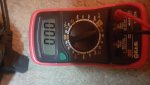
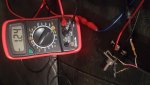
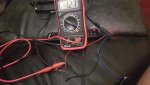
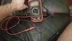
Getting a reading off pedal think we're good there see pic

The brake pedal well first of all getting a beep then I wasn't then even tho I got a beep stayed on o.o2v and new that wernt right had a look and the brake sensor had come loose adjusted it to its correct distance and beep every time 0.00 also does make alot of sense now as... at first the motor was spinning and would just stop as if the brakes were bein applied and only moving slowly some time, and somtimes not doing anything at all, ? Does that make sence to you why the motor wasn't working ...? Im shore I had by passed it tho... but continuity is good there now :)
Thankyou
Tony
 

Attachments

  • 20200304_211342.jpg
    20200304_211342.jpg
    196 KB · Views: 1
  • 20200304_205346.jpg
    20200304_205346.jpg
    235.1 KB · Views: 3

itsid

Moderator
Staff member
Messages
11,563
Reaction score
248
Location
Ruhrpott [Germany]
Uhm ...
throttle was tested incorrectly..
red probe to white wire
and black to blue (but since you remove the plastic connector case now, just connect the black probe to the black wire instead.
And FULLY depress the pedal to give me that reading.

And since that's the case, please repeat the test with the switch once more
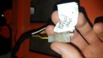
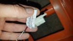
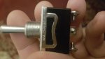
or post a pic of it's underside (I must be able to read the label stamping on the terminals)
I would've loved to be able to read the partnumber so I could've maybe googled the datasheet.. but that's just too blurry.


The brake pedal I understand had a problem with a faulty connection that you now fixed..
yes if that's the case yes the controller might have thought you wanted to stop and shut the motor down.
That would indeed make sense.

So.. this is looking good.

Now comes the time I guess :D

Please DO EXACTLY as I ask you,
do NOT connect anything you think you should.

only connect the following to the controller:
Motor Phase wires and sensor plug.
Batteries.
Throttle.

Short the black and yellow wire on the forward reverse plug
and short the red and orange wire from the ignition plug.

very gently push the throttle and please tell me the motor is now turning over.

If it does,
remove the ignition wire jumper
and install the key switch instead (all still on your bench, NOT in the kart)
switch it on, try the throttle to see if it runs...
and if successfull switch it back off,
connect the brake pedal, switch it back on and test if the motor still runs when throttle is depressed.


Ideally I would want to see what happens as you're doing it (means if you can I'd love a video of that process)
But a good description of what failed and what worked works too.

'sid
 

Tony86

New member
Messages
96
Reaction score
0
Location
London
Sent pics of the forward and reverse switch
And I tho k I did it right this time I checked the throttle with ebike tester and light got brighter the more I pushed it down feeling confident that works even tho nothing happened when pressing it down on this test
Thankyou tony
 

Attachments

  • 20200305_032938.jpg
    20200305_032938.jpg
    128.4 KB · Views: 2
  • 20200305_032930.jpg
    20200305_032930.jpg
    141.4 KB · Views: 2
  • 20200305_032334.jpg
    20200305_032334.jpg
    243 KB · Views: 3
  • 20200305_032420.jpg
    20200305_032420.jpg
    222.5 KB · Views: 2

itsid

Moderator
Staff member
Messages
11,563
Reaction score
248
Location
Ruhrpott [Germany]
1.27Volts with the throttle fully depressed is a bit weak;
I'm hoping it's just the arduino not providing enough power here for some reason (although it should)
the value should be somewhere between 4.3 and 4.7 Volts really

Anyhow, it's a positive signal and we can deal with it being a bit low later on..

If nothing happened without the brake attached,
make sure you haven't forgotten the forward/reverse switch to have one direction set
switch the controller off (ignition switch)
add a jumper wire to the brake pedal plug on the controller (white black! [not the white orange one!!])
power it back on and try again.

And if that too fails.. switch it off,
add another jumper wire between black and green on the plug that says "stalls"

switch it back on and try once more.

Let me know if somethings turning now.

IF NOT:
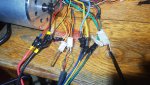
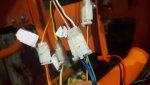
take a picture of all the individual connectors on the controller and how the connections
have been made.

'sid
 

Tony86

New member
Messages
96
Reaction score
0
Location
London
Omg it worked tryed motor 3 can't believe it gonna do the other checks now :thumbsup: must of bin shorting the brake wire or doing somthing really thick... this is gonna work ino it , key switch always worked , and ignition , but gonna prepare the car as its up stairs and bring it down :) :)

She's alive all switches are working, but I've lost the speed switch key ... can you tell me how to put it into top gear for now please? ill send pic and do you recommend a cut out switch? As I have one from the last setup that was onit?

Motor 2 seems to be wanting to work spins a little bit but stops ive but that 1 to the side .. that was using the same controller that worked to .

Thankyou tony
 

Attachments

  • 20200305_115021.jpg
    20200305_115021.jpg
    393.9 KB · Views: 6
  • 20200305_122522.jpg
    20200305_122522.jpg
    144.4 KB · Views: 3

itsid

Moderator
Staff member
Messages
11,563
Reaction score
248
Location
Ruhrpott [Germany]
Great a running motor :wai::wai:


From the pic I'm assuming you do NOT have the brake plug on the controller connected or shorted, is that right?
And please tell me if the brake pedal 'beeps' on it being pressed, or it being relaxed.
(Again... I think I asked about that already.. :()

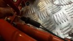
Now I need to ask you to crawl under the kart I'm afraid and take a photo of the
actual switch on the brake pedal;
if it's screwed on.. it also makes sense to remove it in order to get a better view.
I'm especially interested in it's terminals (where the wires connect)


No, I'm afraid I cannot tell you which off the two wires is the higher speed setting.
According to the ebay-pic you posted on page#1 it's a "2 Speed" not a "3 Speed"
so chances are it indeed needs one connection to be made.
which one is faster is easy to determine by simply driving it in both positions for tests ;)
if green/black seems to be slow and sluggish then blue/black would be the only alternative I guess.
Then again you neatly shoved it out of sight for the first shot..
so it shouldn't have be connected when the motor ran, right?


cut out switch? you mean one that fully disconnects the battery?
Then yes, that should be a good idea.

'sid
 

Tony86

New member
Messages
96
Reaction score
0
Location
London
Yes I plugged it in and still working with all connections.
Yes the brake did beep properly after messing the the sensor switch distance , and mine is a proper hydrolic disk brake no wires underneath see pic ...
Yes the motor was connected the same as the last I was expecting somthing like this although does make me skeptical it might do it again and at that time it worked fine at that moment.... but I'm gonna give it ago and hope that it works and the short somewhere is on motor 2 that caused it to not run right????
Also there was somthing I was ment to say but i cant remember really bugging me ....
Thankyou

Tony
•MERGED•
I remember now... to reverse the motor was it yellow to blue and blue to yellow if I remember rightly not a 100 percent ? Nearly finished had to change the cogg to as there was to much play it had a few motors replaced on 1 cogg so it's ok, nearly put her all together but it's taken all day just need to put last few bits back together and will see again if it worked ... It better :surrender: haha should be finished in a hour :)
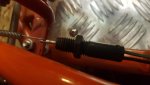
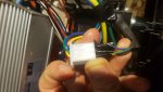
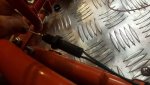
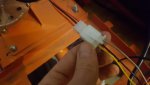
Can you check I wired the forward and reverse correctly as its not engaging and besides that bein wrong or the sensor on the brake has moved again I have no idea besides that last problem bein part of this problem also ?
No continuity in the brake switch seems to have completly failed opening up the sensor to see if I can see anything inside
Thankyou tony
 

Attachments

  • 20200305_181026.jpg
    20200305_181026.jpg
    187.4 KB · Views: 5
  • 20200305_181045.jpg
    20200305_181045.jpg
    178.2 KB · Views: 4
  • 20200305_191829.jpg
    20200305_191829.jpg
    185.2 KB · Views: 4
  • 20200306_002547.jpg
    20200306_002547.jpg
    162.9 KB · Views: 4
  • 20200306_002614.jpg
    20200306_002614.jpg
    149.4 KB · Views: 3
Last edited by a moderator:

itsid

Moderator
Staff member
Messages
11,563
Reaction score
248
Location
Ruhrpott [Germany]
NOOO Tony stop that pleaseeeee

No do NOT swap phase wires, leave them color coded!
(you have a forward reverse switch, let IT take care of phase switching how it's meant to be!!)

You still haven't answered my question!
if the brake always beeps that's wrong!
it must either beep ONLY when depressed or
ONLY when at rest.
WHICH ONE IS IT??

Post a pic of what you "adjusted" .. the sensor switch distance
the switch (I don't care about the mechanical brake at all :()

And as I told you plenty of times you shouldn't have connected the forward reverse switch anyways yet..
you're again rushing ahead and -yes I'm afraid- making wrong assumptions conenctions and eventually ending up just where we started 7 pages ago.

ONE BY ONE and please for the sake of my mental health..
ANSWER MY QUESTIONS!!

like the brake pedal dilemma...
and worse I asked about four times for the bottom view of the switch you got..
the one you just wired up and connected taping all the important bit shut.

Currently you are making it WORSE again I'm afraid.

'sid
 

Tony86

New member
Messages
96
Reaction score
0
Location
London
No not phase wires the hall sensor for motor rotation?
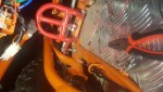
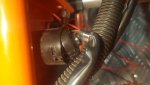
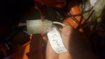
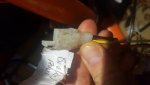
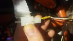
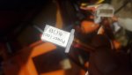
I have no continuity at the brake sensor when pushing it down whats so ever ... I pointed to it at the pic that's all it is .... it was working yestaday when adjusted it now its not doing nothing with my adjustments something is broken in there I'm sure ? Can't get no continuity what so ever and I'm trying to answer your question to that brake switch I hope I have in the pic me pointing at it a pieace of metal on the string pulls it out attattched to the brake pedal .
Was trying to get it done but looks like I need a new part unless I can see inside the sensor and see a short in there see pic ill show you again , if you see the pic one is me not pulling it and another one is when pulled it should beep and there's nothing happening what so ever
Thankyou
Tony
 

Tony86

New member
Messages
96
Reaction score
0
Location
London
I hope I answered your question so I sent all the switch of the whole brake system
Thankyou tony
 

Attachments

  • 20200306_012258.jpg
    20200306_012258.jpg
    126.2 KB · Views: 4
  • 20200306_012247.jpg
    20200306_012247.jpg
    222.3 KB · Views: 4
  • 20200306_012854.jpg
    20200306_012854.jpg
    174 KB · Views: 3
  • 20200306_012946.jpg
    20200306_012946.jpg
    135.2 KB · Views: 3

itsid

Moderator
Staff member
Messages
11,563
Reaction score
248
Location
Ruhrpott [Germany]
NO, not the phase wires, not the hall effect wires.. ALL COLOR MATCHING.

first you said you had continuity, now you don't.. *shrugs*
remove that white plastic box from the kart and take really good pictures of it then.
funny how I see everything else much better than the thing I asked for..

without it properly working, you MUST NOT wire up the motor and controller on the kart!!!

it'll burn out the controller in a matter of seconds when testdriving it!
hence me asking over and over again.

Yes, I'm actually mad right now.. I asked a million times for you to be patient,
so much so that you got annoyed by that..
so I promised to stop asking if you promise to just be.

And the very next occasion you are wildy wiring up things
and blindly poking around ignoring all my requests.
refuse to show me the important bits I asked for and so on...

Okay.. now for the very last time I will ask once more:

Post sharp wel lit images of EVERY
single bit of electronics
especially interesting is the connections side of things..
what terminals, number, layout, MARKINGS!
For switches Top AND Bottom!

if somethings tucked away and bolted to the kart you will likely have to remove it
in order to take a good picture.

And once more:
DO NOT CONNECT ANYTHING I haven't told you to connect just yet.
We need to KNOW first..
or you can fry your controller.


'sid
 

Tony86

New member
Messages
96
Reaction score
0
Location
London
I've ****ed up I have just realised I connected motor 2 instead of motor 3 my bad:mad2:

I have fixed the brake switch again it has a loose clip missing on the switch so it was comming loose I have fixed that ...

Sorry don't always understand what your asking of me...x I have to read it 100 times to understand it to in the end of my best efforts still get it wrong:mad2:

I will try motor 3 if I have enough time tomorrow to finish it would of helped as we new there was issues with motor 2 can't believe I did that.... spent all day and night onit to get it done ....I have done a professional job on wireing it to although ill have to take it all off i will still send pics but it would off helped using the working motor oviously ....
Thankyou tony
 

Attachments

  • 20200306_031726.jpg
    20200306_031726.jpg
    148.7 KB · Views: 2
  • 20200306_031740.jpg
    20200306_031740.jpg
    131.2 KB · Views: 4
  • 20200306_031758.jpg
    20200306_031758.jpg
    128.9 KB · Views: 5
  • 20200306_031913.jpg
    20200306_031913.jpg
    250 KB · Views: 3
  • 20200306_032001.jpg
    20200306_032001.jpg
    164 KB · Views: 2
  • 20200306_031715.jpg
    20200306_031715.jpg
    137.4 KB · Views: 4
  • 20200306_031619.jpg
    20200306_031619.jpg
    156.7 KB · Views: 74
  • 20200306_031556.jpg
    20200306_031556.jpg
    133.6 KB · Views: 3
  • 20200306_031527.jpg
    20200306_031527.jpg
    154.1 KB · Views: 4
  • 20200306_031524.jpg
    20200306_031524.jpg
    193.5 KB · Views: 3

Tony86

New member
Messages
96
Reaction score
0
Location
London
More pics
 

Attachments

  • 20200306_030936.jpg
    20200306_030936.jpg
    104.3 KB · Views: 3
  • 20200306_031014.jpg
    20200306_031014.jpg
    119.7 KB · Views: 3
  • 20200306_031053.jpg
    20200306_031053.jpg
    126.9 KB · Views: 3
  • 20200306_031114.jpg
    20200306_031114.jpg
    107 KB · Views: 3
  • 20200306_031120.jpg
    20200306_031120.jpg
    114.9 KB · Views: 1
  • 20200306_025756.jpg
    20200306_025756.jpg
    137.1 KB · Views: 3
  • 20200306_025806.jpg
    20200306_025806.jpg
    115.9 KB · Views: 3
  • 20200306_025851.jpg
    20200306_025851.jpg
    139 KB · Views: 4
  • 20200306_025903.jpg
    20200306_025903.jpg
    112.5 KB · Views: 4
  • 20200306_025912.jpg
    20200306_025912.jpg
    140.8 KB · Views: 3

Tony86

New member
Messages
96
Reaction score
0
Location
London
Few more pics
 

Attachments

  • 20200306_025303.jpg
    20200306_025303.jpg
    167.4 KB · Views: 4
  • 20200306_025256.jpg
    20200306_025256.jpg
    192.3 KB · Views: 3
  • 20200306_025243.jpg
    20200306_025243.jpg
    156.1 KB · Views: 1
  • 20200306_012247.jpg
    20200306_012247.jpg
    222.3 KB · Views: 2
  • 20200306_002614.jpg
    20200306_002614.jpg
    149.4 KB · Views: 3

itsid

Moderator
Staff member
Messages
11,563
Reaction score
248
Location
Ruhrpott [Germany]
Thank you Tony!

Sorry for being mean,
I know that you have a hard time reading my replies and
are trying to fullfill my requests.

But I want to make sure you're succeeding this time with the installation,
and a faulty part or a misconnected one can be
the cause of you not succeeding before...
and quite possibly the reason at least one motor and maybe even a controller are dead by now.

I couldn't watch you run into the same trap again,
that's why I'm so overly cautious about connecting untested wires/switches.

I'll go over the images later and see if there's anything missing
that I'd need to make you a definitive wiring diagram.

'sid
 
Top