You are using an out of date browser. It may not display this or other websites correctly.
You should upgrade or use an alternative browser.
You should upgrade or use an alternative browser.
48v 1000 go kart upgrade to 1800w
- Thread starter Tony86
- Start date
 I sent you a pic m8
well you cannot have uploaded the blink sketch with that I'm afraid..
something must've been changed or the arduino came preloaded with the blink sketch already.
Anyways..
with the Arduino NOT Connected to the Computer
check Tools-> Port to see what entries are listed (remember them!)
if it's greyed out.. the list is empty (appears to be *shrugs*)
connect the Arduino Nano via USB,
then open Tools->Board and select "Arduino Nano" from the list of boards.
go to Tools->Port and select the Port Number that wasn't there when you checked first.
(maybe the only one in there now)
click "Get Board Info"
and post the resulting message.
if "Port" is still greyed out,
with the arduino still conneced
open the Windows device manager
(here's how to find it in case you need help https://www.computerhope.com/issues/ch000833.htm)
And then expand the view for "Ports (COM & LPT)"
and check if you see an entry called "USB-SERIAL CH340"
if you don't you forgot to install the ch340 driver")
Install it now and see if it appears in the device manager.
if it does go back
to Arduino IDE Tools->Port and see if you can now select a COM Port.
'sid
something must've been changed or the arduino came preloaded with the blink sketch already.
Anyways..
with the Arduino NOT Connected to the Computer
check Tools-> Port to see what entries are listed (remember them!)
if it's greyed out.. the list is empty (appears to be *shrugs*)
connect the Arduino Nano via USB,
then open Tools->Board and select "Arduino Nano" from the list of boards.
go to Tools->Port and select the Port Number that wasn't there when you checked first.
(maybe the only one in there now)
click "Get Board Info"
and post the resulting message.
if "Port" is still greyed out,
with the arduino still conneced
open the Windows device manager
(here's how to find it in case you need help https://www.computerhope.com/issues/ch000833.htm)
And then expand the view for "Ports (COM & LPT)"
and check if you see an entry called "USB-SERIAL CH340"
if you don't you forgot to install the ch340 driver
Install it now and see if it appears in the device manager.
if it does go back
to Arduino IDE Tools->Port and see if you can now select a COM Port.
'sid


Ahhh .. more pics.. good yes almost there
avr mkII not working, swap "Programmer" to "arduino"
'sid
avr mkII not working, swap "Programmer" to "arduino"
'sid
okay here's what my tools-menu looks like at the important area:

So make sure Programmer is set to "ArduinoISP"
(take care there are similar entries.. you want the one without any addition or spaces)
chances are your's is using the old bootloader as well...
so try changing that if you get an error uploading the sketch.
and if it still fails, it might be without ANY bootloader as of now, in that case open tools and click on "Burn bootloader"
then wait.
All important output is in the lower portion of the Arduino IDE window
you can move the gree bar up so you see more of those debug/error console
just mark the text with your mouse and press CTRL+C to copy it,
then paste it here
(ideally in [code] <text> [/code] brackets)
'sid

if there's a problem with the sketch, then the debug log will tell you..
just show me the debug/error log (black portion of the arduino ide)
'sid
just show me the debug/error log (black portion of the arduino ide)
'sid
with the arduino connected, open up the serial monitor
and see if you can already read it's output
should read (with no wires attached)
if the serial monitor remains blank, then something's missing
(either the sketch wasn't uploaded or the com port isn't the correct one or IDK... we'll have to find out then)
'sid
and see if you can already read it's output
should read (with no wires attached)
Code:
Welcome, please follow the instructions!
Setting up treshhold, please DO NOT move the motor shaft!
--done--
Rotate Motor shaft 1 notch clockwise! (1 of 18)(either the sketch wasn't uploaded or the com port isn't the correct one or IDK... we'll have to find out then)
'sid

perfect....
I just modified the sketch however..
so now it can handle both the "original" motor configuration as well as the one with the replacement ss495 analog reading sensor
(find it attached)
No need to update your arduino code as of now,
but once you want to test the other two motors, we'll need that instead
'sid
PS if the wires don't arrive till friday, I'd suggest we just use what you have to move on quick enough for kiddo's birthday in 10 days... what'd you say?
Attachments
Wicked Sid and yeah that would be awesome but we get would we can get done not the end of the world but would be a nice surprise thankyou drilled a whole through the car so the switch is ready to be installed just got to put it all back together which is gonna take some time... If it still lags a bit and gets really hot I'd like to boost some extra Amps if possible? The original motor for on grass plus the fact it weighed a ton... would burn out so quick and get so hot but for now we will see how it performs the car hopeing the upgrade will give it the power it needs to run smoothly
Many thank Sid
Tony
but we get would we can get done not the end of the world but would be a nice surprise thankyou drilled a whole through the car so the switch is ready to be installed just got to put it all back together which is gonna take some time... If it still lags a bit and gets really hot I'd like to boost some extra Amps if possible? The original motor for on grass plus the fact it weighed a ton... would burn out so quick and get so hot but for now we will see how it performs the car hopeing the upgrade will give it the power it needs to run smoothly Many thank Sid
Tony
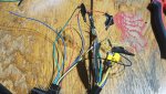
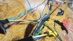
ideally remove ALL wiring from the kart and start from scratch.
Throttle andd brake, as well as the battery indicator are the only three things
that do not need rewiring.
DO NOT leave in any switches whatsoever
(those switches from the dashboard you showed earlier 132 and RPD have to go and so does ALL their wiring!!)
that thing was incorrectly setup for your motor controller kit,
and if you leave any of that shirt on, we'll not be able to get this going!
that's why I suggested to putz the switch there in the first place (since those two switches MUST BE REMOVED!)
Sorry, not screaming, just emphasizing
'sid
PS see you tomorrow then (technically it's thursday already)
are you sure the 132 is the wrong setup I really wanted to keep that? I had it working in all gears and goes to the switch with matching wires? The RPD totally agree wrong setup entirely....* why would the throttle and other things when they all match up with the wires ? Besides them either being wrong thickness in wire? Or shorted out ?* Just curious? For future referenceNo I'm not sure it's wrong...
in fact I'm fairly certain it's useable
BUT and that's the important point: I have no clue how it's wires are fed front to back, and how the switch actually acts internally..
and in case it is wrong, it might fry the controller and we start from scratch again.
So my thinking is this:
remove all unknowns first!
that way we stay safe and ONLY move
forward towards our goal and
never have to backtrace a problem.
Once that switch is safely removed and laying on your table, we can test that, label that properly and IF (and only if) it is indeed as we both think it is,
THEN we just screw it back in place and take it to work...
No untested part will be used.. you spend more than enough for parts already,
and I don't want (I would really want to avoid you) buying more parts,
especially if we can avoid that by being extra cautious before we
make any connection with the controller.
And since we test only one part after another to make sure we haven't skipped something by jumping back and forth.. it's far back on our to do list
For future reference the To Do List:
'sid
in fact I'm fairly certain it's useable
BUT and that's the important point: I have no clue how it's wires are fed front to back, and how the switch actually acts internally..
and in case it is wrong, it might fry the controller and we start from scratch again.
So my thinking is this:
remove all unknowns first!
that way we stay safe and ONLY move
forward towards our goal and
never have to backtrace a problem.
Once that switch is safely removed and laying on your table, we can test that, label that properly and IF (and only if) it is indeed as we both think it is,
THEN we just screw it back in place and take it to work...
No untested part will be used.. you spend more than enough for parts already,
and I don't want (I would really want to avoid you) buying more parts,
especially if we can avoid that by being extra cautious before we
make any connection with the controller.
And since we test only one part after another to make sure we haven't skipped something by jumping back and forth.. it's far back on our to do list
For future reference the To Do List:
- we checked the controller (hopefully all but at least one)
- next up is the motor (hopefully all of them)
- followed by testing the throttle pedal and brake pedal.
- then we will wire the main power (key)
and the two pedals correctly.
and at this point nothing else should be connected to the controller.
- then we do a short system test (testrun of the kart).
And after that is successfull, - we care about the speed limiting switch, the forward reverse switch
and the battery monitor
'sid
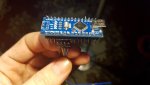
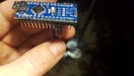
Before I plug it in just want to double check everything is correct hall sensor matching to auduino , should I connect the odd blue 1 to the ss495 aswell??and then put it in the motor keeping it stable so that the sensor will ready it in its correct area, then plug in the auduino?
Thankyou
Tony
Thankyou
Tony
Attachments
-
 20200227_224756.jpg142.6 KB · Views: 1
 -
 20200227_224811.jpg153.9 KB · Views: 1
 -
 20200227_235531.jpg398 KB · Views: 1
 -
 20200227_235544.jpg322.9 KB · Views: 2
 -
 20200227_235653.jpg305.9 KB · Views: 1
Sorry, morpheus caught me on the couch
Yepp that's all correct..
I'm still unsure if that tantal cap has enough room inside the motor case.
But since we don't need to power the motor just turn the shaft by hand I hope it'll be fine.
Now, insert the HE sensor to the sensor xcasing inside the motor housing,
solder it to the original sensor wires
bend the cap out of the way so you can reinstall the motor end cap
(we need the rotor to be in two bearings to not hit the stator)
And then... there'll be nothing left but to connect the arduino to the USB power of yopur computer and follow the instructions of the serial monitor.
I'll have my fingers crossed.
'sid
Sorry completly lost me there...
so put the sensor in attached to bead and blue wire?
see if it spins ?
If so connect the sensor to its original wires ?
Would that be the correct sensor then?
If so I'll hot glue it down and put it away tidy?
And close the motor back up ?
Then I can start plugging in the usb on laptop etc?
I got a feeling it won't as if I remember rightly when I sent you a pic I think we see another sensor had shorted out at the bottom? On the black wire ?
Thankyou tony