48v 1000 go kart upgrade to 1800w

itsid

Moderator
Staff member
Messages
11,564
Reaction score
116
Location
Ruhrpott [Germany]
Oh missed that post, sorry.

So.. cut of three pieces of the red wire (each 12cm long)
and one piece of the black wire (also 12cm long)
remove 1cm of insulation on each end of all the pieces and tin them with solder.

Now take the 10k Ohm resistor (brown black orange gold stripes)
and solder a red wire to each end.

then take the 1.8K Ohme resistor (brown grey red gold stripes)
and solder the remaining red wire to one end and the black wire to the other end.

lay the bare metal lead of the resistor on the RED side across the bare lead of
the other prepared wire (doesn't mater which side since both are red anyways)
and solder them together

take a picture of that and show me your result ;)
if you're stuck somewhere just show me what you did (again with a pic)

it should look roughly like that ( the pic in post #47)


'sid
 

Tony86

New member
Messages
96
Reaction score
0
Location
London
That seems ok? The 2 ends of the resisters join together? as in the pic?
Thankyou

tony
 

Attachments

  • 20200216_205551.jpg
    20200216_205551.jpg
    339.7 KB · Views: 13

itsid

Moderator
Staff member
Messages
11,564
Reaction score
116
Location
Ruhrpott [Germany]
Great, yes I was expecting something like that..
(tbh I'd made it differently.. but that's extremely close to what I drew and certainly correct!)

Those look to be five band resistors
(I was expeting four band colour codes)
would you please verify the colors for each resistor for me
just to soothe my curiosity
I can't make them out too well on the photo I'm afraid
just in case that second to last stripe is not just a weird shadow.

For future reference I will from now on refere to the left half of the pic
(black and red leads left of the resistors)
as the INPUT
and the right side (the two parallel red wires right of the resistors)
as the OUTPUT
since that's how we will use them :D

Moving on:
Now please use some shrink tube to cover the bare metal part of the red input wire
just to make sure it cannot short out against the same bit on the black input wire ;)
that could damage the controller and we want to avoid that.

Of to the preliminary test:
check if you can wedge the tinned ends of the input wires into the power leads
on the Hall Sensor plug of your controller (red to red, black to black)
if you cannot;
I'm afraid I'd like to ask you to add the proper spade connectors to all four tinned ends.
(you said you had those laying around, right?)

Once connected, get your multimeter out and set it to 2V DC testing range.

connect the controller to the battery (nothing but battery and power switch)
and power it up just as you did for testing the voltage on that plug.

Touch the bare metal on the INPUT side
(black!.. we covered red to avoid mistakes remember?)
with the black probe and any red wire end with the red probe.
you should read a voltage between 700 and 830 mV
(it'll read as 0.700 - 0.830)
move the red probe around to behind any resistor, between the soldered ends and the two output wires.
that should all be more or less identical values all in the above range.

please let me know what exact value you got on the output ends
and in case you're outside of that range, please take a picture of what's connected how
and the multimeter in shot.

you might already want to
grab some duck tape or gaffa so that you can fix wires to your bench in a secure way.
and if you have, a pair of rubber gloves might come in handy as well
(like rubberized working gloves or such)
in case you have alligator clips for your testing probes,
those might make things easier for us as well.
The only important part is the duck/gaffa tape..
the rest is really not all that necessary, just adds a bit of convenience

(DO NOT YET! just get prepared):
the next step will be that we touch the HE sensor lines with the red output wires
to fake a correct hall sensor response, that should trigger the phase wires
to engage; so that we can test if the phase wires actually turn on and swap direction properly.

'sid
 

Tony86

New member
Messages
96
Reaction score
0
Location
London
I think i did this right find that so hard to read and do ... read it like 100 times give me headache haha not your fault.... see attached pics I got 658 if I did that right? For some reason this post did not come through email I will check for frequent
Thankyou
Tony
 

Attachments

  • Screenshot_20200218-023514_Samsung Internet.jpg
    Screenshot_20200218-023514_Samsung Internet.jpg
    818.9 KB · Views: 5
  • 20200218_022701.jpg
    20200218_022701.jpg
    243.7 KB · Views: 6
  • 20200218_022723.jpg
    20200218_022723.jpg
    264.2 KB · Views: 8
  • 20200218_024356.jpg
    20200218_024356.jpg
    228.5 KB · Views: 5
  • 20200218_024347.jpg
    20200218_024347.jpg
    240.8 KB · Views: 3

itsid

Moderator
Staff member
Messages
11,564
Reaction score
116
Location
Ruhrpott [Germany]
well, almost I guess ;)

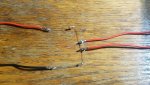
a) where's the color sequence, you just posted that same image again,
this time as a screen shot (which is in fact LESS helpfull)

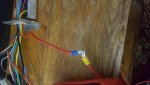
b) you wrapped the black wire in shrink as well
(too bad, now we lost the negative easy access terminal)
since battery is not a good source! (leave it as is please...)

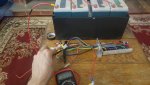
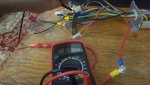
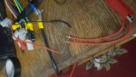
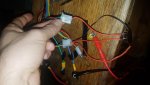
c) I can't see much on your crowded bench..
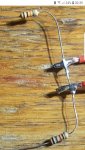
the red probe is conencted properly, but where's the black one?
I sincerely hope it's the one you hold in the second pic and
that that's the HE conenctor. (can't tell for sure :()
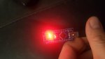
If it is, we're golden.. 658 is a perfectly reasonable value to read!
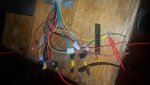
(and the resistors are of a good enough precision and in correct order.. leave them shrinkwrapped as they are)

if however you used any other than the HE connector as a ground for your multimeter probe,
the value might be off (unlikely by much so I'm still willing to call it good.. but I'm not exactly happy ;))

yes I said you want 700.. but remember I asked you about the exact value for the HE power connectors?
and you just replied with a roundabout 5V?
that's a direct result ;)

No worries.. all good :thumbsup:

BUT this is important:
you really need to take care in this next step,
don't wing it, don't rush it, and be -for the sake of your personal health- careful what you do!
make sure your kid isn't coming "helping dad" inadvertently touching anything... what can severly harm an adult, does worse to younger thinner skinned humanoids!
rather bark her off than have her hurt!

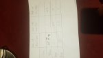
draw yourself a phase table
exactly like that please:
Code:
	 black - red	  black - red 	  black - red
	|yellow / green	|green / blue	|blue / yellow
-------------------------------------------------------
none	|		|		|		
-------------------------------------------------------
yellow	|		|		|		
-------------------------------------------------------
green	|		|		|		
-------------------------------------------------------
blue	|		|		|
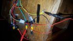
Now, take the gaffa tape,
and tape down the motor phase wires to your table, take care that they're well spread out
(20 cm or more) so you cannot accidentally touch two with one hand.
This is important!
any mishap with a powered up phase you short with your hand can cause a severe electrical burn.. (wear rubberized gloves if you have)

reconnect the battery (ideally wrap the connectors in gaffa too),
connect the patch cable as before (taking power from the HE connector itself)
engage the powerswitch (or bridge) to power the controller up.

Set your multimeter to 200V DC and
  1. clamp it's black probe to the yellow and
    the red one to the green phase wire.

    • if you now read a voltage already, write it down in the
      "none" - row (add a sign for voltage direction!)

    • now take one of the red output wires of our patch cable
      and connect it to the yellow wire on the HE connector.
      write down the Voltage (again directionally signed)

    • move the patch output wire to the green on the HE connector, write the Voltage down

    • finally move it on to the blue wire on the HE conenctor and write down the voltage

  2. remove the red probe from the green phase wire and move it to the blue phase wire,
    then move the black probe to the green
    and repeat the steps a-d for the second column

  3. move the red probe to the yellow phase wire,
    then the black to the blue phase wire and repeat a-d for the third column

if all you got was zero volts all the way.. not all is lost,
we just need to trick the controller into thinking we have a throttle signal.
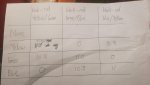
if you got a voltage on all three columns at least once
you can stop here and just show me the table.

Else draw another such phase table if yours is now filled with zeros
(sorry for the hassle I was hoping for a minimal signal on the phases)
write down 0.7V throttle at some corner to not mess the two tables up.

take that second output wire of our patch cable and connect it to the signal wire on the throttle connector (should be green I think), that way we fake a low throttle signal (nothing close to full power but surely detectable)

ideally tape the throttle connector and that patch cable output down too,
so it cannot come loose while we use the other output wire to repeat the above steps all over again.

and then take a snapshot of that table to show me the results.

Make sure to disconnect the controller from the battery (safety first and such)

I think we can now make a good call about the state of the controller already.
chances are slim but not impossible that we got a weird result
(one phase working the other ones not or such)
but that might be just based on us not treating the controller as a motor would and it got slightly confused by our pokings;)
if so we might need to conduct a second experiment alike
just way more complicated..
so please - for now- leave the phase wires taped down to the bench ;)

'sid
 

Tony86

New member
Messages
96
Reaction score
0
Location
London
I got nothing out of all of that? s3nding pics to see if I worked it right , wired up the throttle with the other output red wire still nothing if correct so worried I'm gonna do more damage than good ... I hope I can fix this because we talk bout patience I've experienced more patience with this car than anything I've ever done in my whole life thats no lie in ready to throw in the towl and I ain't got much left in me tbh sucking the life force out of me turning me greyer by the day haha would rather send it to you did if we don't see any improvements soon bringing me down :(
 

Attachments

  • 20200218_194715.jpg
    20200218_194715.jpg
    301.8 KB · Views: 2
  • 20200218_193931.jpg
    20200218_193931.jpg
    314.6 KB · Views: 1
  • 20200218_195409.jpg
    20200218_195409.jpg
    245.7 KB · Views: 2
  • 20200218_200027.jpg
    20200218_200027.jpg
    322.4 KB · Views: 4

itsid

Moderator
Staff member
Messages
11,564
Reaction score
116
Location
Ruhrpott [Germany]
That looks about right,
terribly crowded pics though
(I know, not your fault at all.. it's just the way it is when you work with a crap ton of wiring)
but a better lighting wouldn't harm .. nevermind;)
The more I can see on the image (all connections I can identify and trace properly)
the less I need to ask you to verify ...

Talking about it:
I told earlier you to remove the forward reverse connector (black-yellow-grey connector IIRC)
you made, right?

I can't tell from the pics if that's indeed gone...
We need that back again of course (sorry.. I forgot about it)
So black to yellow again and one more try.

battery connected, forward reverse connected (black to either yellow or grey)
and main power connected (red and orange connector)

If you still get nothing, maybe green is not the signal wire on the throttle connector,
that'd be odd but not unseen on chinese "we colour as we want" type of controllers.

And to give you a head start on that (not having to wait for another reply of mine)

Look on your controller board in the lower righthand corner
where all the small wires connect to.
In the rightmost column,
you should see the
top most position as SV (likely unpopulated)
the one below as 4.3V (that wire should go to the throttle connector)
the one below that as SD (that too should go to the throttle connector)
and the one below that as GND (one of which also going to the throttle connector)
The SD wire is the one I suspect to carry the signal back into the controller.
trace those wires to the connector to make sure that's the throttle!
(since they all vanish in that grommet..
just gently pull on the wire in question to see what connector reacts to that)

clearly identify the GND wire (likely black but who knows)
then set the multimeter to 20V and test both
non GND wires on the throttle connector against it
one should show 0Volts and the other 4.3V or more.

ONLY if you have found one to be 4.3V or more and the other to be 0V,
you can be sure the 0V wire is the one we are actually looking for.
That is where the second output wire should be conencted to when testing.

In case you got no result that would make sense to you
I'd like to ask for two crystal clear images of the lower right corner of your controller
where the wires connect, front and back of the PCB.

'sid
 

Tony86

New member
Messages
96
Reaction score
0
Location
London
This pic is clear if it is still the green I will test the same with forward and reverse plugged in together?
I apologise for my rant just got alot going on ...and a bit dyslexia so makes it even harder so please if you can just use simple terms and words to describe things hence why I asked to communicate other ways as on top this makes it more difficult for me and more likely make a mistake but you explained it all pretty good just bare that in mind
Thankyou so much

Tony
 

Attachments

  • 20200219_023133.jpg
    20200219_023133.jpg
    142.7 KB · Views: 2
  • Screenshot_20200219-024227_Gallery.jpg
    Screenshot_20200219-024227_Gallery.jpg
    1,000 KB · Views: 2

itsid

Moderator
Staff member
Messages
11,564
Reaction score
116
Location
Ruhrpott [Germany]
I known I'm annyoing with that "be patient, take your time, be carefull"
stuff, but whenever the controller is under power,
the currents involved can severely hurt a human,
and we can never be too sure the low voltage will prevent a serious injury.

But if you promise me that you will ALWAYS be super cautious around the controller as soon as it's connected to the battery, and take care not to short out anything or touch any lead with your bare hands.
I will tame it down to the bare miniumum :D

Now.. yes that pic is what I was asking for.
and yes it appears green is the wire we want.
BUT maybe it's labelled the wrong way around for some reason or another.
So please with the controller powered up. (battery connected, power jumper installed)
measure the voltage between black and red (should read 4.3V)
and confirm by measuring the voltage between black and green (should read 0V maybe some 0.05V ripples)
Then yes.. green is our Sensor Data.

And yes, please reconnect the yellow and black from the forward/reverse connector
and conduct the same test again (that table filling thingy in post #85)
if that also fails, try yellow - grey instead.

IDK the exact wiring layout for the forward/reverse connector I think it's in the second column
on the pcb.. maybe the third.. that might help us figuring it out..
black should be on a GND labelled spot on the pcb..

Finally:
I'll try my best to keep things shorter and easier for you to follow.
but since the colours repeat on the plugs I still need to be precise I'm afraid ;)

And sure.. I wish it'd be cheaper to send that heavy stuff around,
or you to be closer;
then I'd already asked you to just dump that stuff at my door
and I'll send it back properly connected after testing ;)

'sid
 

Tony86

New member
Messages
96
Reaction score
0
Location
London
No its fine bein professional :thumbsup: Cheers ino like you I like to give things ago i do alot of micanics but electric bits like this is another level and between us we dont no how to test this efficiently just even harder like this for me .... and I already burned myself once I spent hours onit and in the stress of the moment on resemble when it didn't work I touched live red battery wire ...ouch, wasnt the worst burn i ever had working at a terrible company with no health and saftey with wheel stripping acid is still the winner ..., and thanks my daughter free roaming rabbit is locked away for this job as they love to chew a wire:thumbsup:

:wai: great news I think we have some good results but not 100% no what it means as each colour on hall has o but I'm sure you will make sence of it :) :)
 

Attachments

  • 20200220_213309.jpg
    20200220_213309.jpg
    134.6 KB · Views: 2
  • 20200220_211600.jpg
    20200220_211600.jpg
    122.2 KB · Views: 1

itsid

Moderator
Staff member
Messages
11,564
Reaction score
116
Location
Ruhrpott [Germany]
Well I know how to test this very efficiently tbh..
but that's nothing I'd advice anyone that never did anything alike before over the internet ;)
Since the tiniest mishap and there will be collateral damage ;)

Now, you forgot to note the signs down.. but I will just ignore that,
it's only important for one following step, and we can just test that later.. no problem!

The good news: the controller is perfectly working.
I expected the numbers to be slightly lower tbh, but I guess that's residue voltage of the internal cap in your multimeter :D

I was a bit afraid that it doesn't have a fallback mode and we had to step over
the correct HallSensor Sequence manually to be honest (which is a bit of a pain)
Luckily that's not the case and we can put the controller aside as a fully working unit.

Yes, it's perfectly correct that the controller shows a zero output on one setting
one of the settings should read a positive value, the other a negative;
I assume the 10.8 to be the negative one.. nevermind.

Please, put the case back on,
screw it tight and use a sticker or a sharpie on it's back
to label it "tested and working"
not to confuse it with the other controller you got.

Now would be a good time to test the second controller in the very same way.
it should yield similar results.

I misplaced my ss495 I'm afraid, so I wasn't able to test the arduino code yet.
I ordered a new one that should be here tomorrow.. maybe on saturday

I'll have the arduino code tested by hopefully tomorrow, maybe saturday (need to wait for my ss495) so I can send it over.

In the meantime go ahead and install the arduino IDE
https://www.arduino.cc/en/main/software
to your computer or laptop

and I think you might need a different driver for your cheap clone to function.
since they use a much cheaper USB driver chip (usually a CH340)
you can take the driver from this website:
https://sparks.gogo.co.nz/ch340.html
install that too.

could you just let me know what type of arduino you got?
with pinheader soldered in or seperate?
I'll try to tke some pictures for you how to easily assemble it;
and I want to match your setup as closely as possible, so it'll be easier to follow.

'sid
 

Tony86

New member
Messages
96
Reaction score
0
Location
London
Awesome:) could you explain that patch work and how 4 gates powered up each switch please?

And yeah have did a lil bit of research on them auduino and that software ...will get that sorted and if I need somthing extra thats no problem :thumbsup:

And sorry you lost that and thank you ever so much for getting a new one for me and the auduino I will refund you that don't worry bout that ....:cheers2:
Thankyou ever so much sid :thumbsup:

Tony
 

Attachments

  • Screenshot_20200221-011301_eBay.jpg
    Screenshot_20200221-011301_eBay.jpg
    351.3 KB · Views: 0

itsid

Moderator
Staff member
Messages
11,564
Reaction score
116
Location
Ruhrpott [Germany]
Nonono.. you don't pay for my sensor.. I ordered it, I'll keep it.. I'll pay it!

so a non pinned arduino it is then, great..
I'll find one for the photo session ;)

You lost me on the 4 gate question I'm afraid
I'll happily explain, but could you rephrase the question ?
I think I didn't quite understand.

'sid
 

Tony86

New member
Messages
96
Reaction score
0
Location
London
Sorry for my late reply haven't seen my daughter in 3 weeks :( so we had alot of fun, on weekend ,

I surpose I'm trying to ask how the 10 ohms and 1.8ohm together made voltage to power up each switch? It was like red and black made up 5volts ? And the other 2 reds was like 1 volt which was enough to power the switch if that makes sence ?
I'm just bout to download the software and I'm ready sid :)
Many thanks
Tony
 

itsid

Moderator
Staff member
Messages
11,564
Reaction score
116
Location
Ruhrpott [Germany]
Ah now I understand..
10k and 1.8k Ohm btw ;)

Well we made ourselves a Voltagedivider using two simple resistors.
How do I explain this...?

Okay, Think of it as distance from A to B. (0 to 5V in our case)
let's picture that as 5000 meters
we now used two resistors in series to to bridge those 5000 meters.
one was of 10000 units long and the other 1800 units long (Ohms here)

Since we know we spanned 5000m over 11800 units
we know each of our units is about 0.424 meters long in this metaphor ;)
(5000/11800 = 0.4237288...)

with the two output wires we connected between the two resistors
we jump off that bridge after just 1800 of those units
and those 1800 units spanned a distance of ~763 meters

Now those 5000 meters are in fact 5000mV and
the 'distance' we used to jump off our 'bridge' therefor was 763mV (or 0.763 V)


We need a relatively low signal of some sort.
I knew the microprocessor that reads the signal (it's not a switch really.. )
can detect very small voltages (the 0.07V that kevin read from the sensors)
And that told me that the controller very likely used a low comparator voltage.
the usual suspect in those cases is 1.1V since that's the internal reference voltage for most microprocessors.
So under all circumstances we needed to make sure we stay below those 1.1V and above the 0.07V we knew about earlier,
to not inadvertently destroy the microprocessor nor get a value too low for it to read.

0.7 ish volts were easy to make with common resistor values
and it's been the first I could come up with in my head, so that's what I told you to use.
Well tbh 0.5V was my first intention, but the colours on the resistor could've ended up too similar
and I was worried I wasn't able to identify them correctly on your pic ;)


'sid

PS magnetic sensor arrived yesterday,
reader seems to be working well but I'd like one more test with a actual BLDC (not me faking one)
 

Tony86

New member
Messages
96
Reaction score
0
Location
London
:thumbsup:I roughly no what you mean not somthing I could do on my own to test anything in future with resistors ....

And yeh no worries, when your ready m8, everything downloaded:). her bday in 2 weeks would be a nice surprise if it got fixed before then but no presure... its done when it's done:thumbsup:

The forward and reverse switch have you ever seen a bar clamp that fits that switch, or anything like that or somthing similar as noing where to put it is going to be a challenge as its all metal frame ,even cable tieing it down maybe difficult to?
Thanks a mill

Tony
 

itsid

Moderator
Staff member
Messages
11,564
Reaction score
116
Location
Ruhrpott [Germany]
I don't have the images taken yet.

the code itself for the motor that you ripped a HE Sensor out is done though.

I assume you have the arduino software installed and the arduino connected properly?
the quickest working test would be the arduino example "blink"
it just uses an internal LED to -well- blink ;)

you did that successfully?
So we know the driver is installed, the correct board selected and so on,
or do I need to help you with that?


If that's done, you can already download the attached zip.
and load the packed ino into the Arduino IDE

I tried my best to make it as simple to read and understand as possible.
If you want me to explain the code, just ask.

But you can already Upload that motorhallread sketch to the Arduino
open the serial monitor from the tools menu (Ctrl+Shift+M)
and see if it's outputting legible data

if it's not, set the baudrate of the serial monitor to 19200
in the lower right corner of the serial monitor.

Do you have any slightly smaller wires or different colours?
Sorry I didn't think of that earlier, I have a bunch of small wires laying around to tinker with and I simply forgot.

if you don't no worries, but we'll need a few bits of painters tape to label each end of the wires just to be sure we're not getting confused. or better yet three different colours of electrical tape

Well the switch should fit where the old switch was located
(you won't need the old one anymore.. so remove it from the kart)
I don't think the ON/OFF/ON switch should be case grounded to the pins we are about to use.
but to tell for sure, take a pic of the switches rear and show me.
(need to be able to read the tiny labels on the pins)
Or even better.. a datasheet of the switch itself ;)

'sid

PS I'll be back with images soon

[EDIT]
Sorry, could you buy a set of jumper wires perhaps,
that's likely the best thing to wire the arduino up for us..
https://www.ebay.co.uk/itm/10pcs-Du...hash=item3d15d6a36d:m:maEwa3WZcppiF84ZCpR-28A
female to male should do nicely..
a set of all three is fairly priced (3 for 2)
but it's just because I'd rather have coloured wires to not give confusing instructions ;)

It's not exactly required (as I said we can do without) I just think it might make things easier for us ;)
 

Attachments

  • motorhallread.zip
    1 KB · Views: 4

itsid

Moderator
Staff member
Messages
11,564
Reaction score
116
Location
Ruhrpott [Germany]
Well then.. images couldn't find the unpopulated arduino anywhere,
must've dropped behind some closet *shrugs*
So a populated must suffice;
and since the previous post was already kinda long I decided I might as well make two :D

we need three wires on the left side of your arduino
connected to D3, D2 and Ground
4701.jpg

an optional fourth blue wire (on D4) can already be put in place if you solder them in,
in case you want to test the motors you haven't removed the HE Sensor from as well.
4702.jpg

And on the other side of the Arduino we need the 5V and the A7 to be populated,
5V red and A7 ideally in blue (that's the one we will need next)
4704.jpg

So those pins will be populated when we're done
4706.jpg

essentially
this is what we want
he-wiring.png

you can see only one of our "blue wires" is used at a time
one will be analog (for the code I posted earlier) and one will
be a digital pin (code yet to come)

You want the arduino connected to the motor's hall effect plug
I haven't seen the hall effect plug so I used a placeholder

Please make sure to have power and ground the right way around black to black (GND on the Arduino) and red to red (5V on the Arduino) of course

if you don't have coloured wires at your disposal and don't want to order a set of patch wires online (not to wait for them)
just use a red wire for the 5V on the arduino and black everywhere else!
then with the help of electrical tape label the ends with their respective numbers.

In the end that all needs to connect to the motor (no controller, no battery) and in order to read the serial output to the computer ;)

Now the tricky part... the SS495 needs to be wedged into the location of the original HE Sensor in your motor.
The problem is the tantal cap... it obviously can't join,
there might be enough room to bend it over the coils,
but I have no way of telling from the pictures.
I'd say you might leave it be and just ignore it for now,
the output signal will likely suffer from the power not being stabilized for the hall sensor,
but that's why I added the threshhold in the code.. to try and compensate that.

So for now I'd say let's try without the tantal cap, and if that doesn't give reliable results we can add it later.

put the ss495 into the cutaway with the narrower side facing the rotor.
and then solder the original wires on..
red closest toward the other two HE Sensors, then black and blue furthest away from the other sensors
crude drawing ahead :(
he_lead wires.jpg

make sure the bare wires can't touch each other, use shrink tube if you can.

Then all that's left to do is actaully close the motor case;
connect the arduino to the motors hall wires (colour matching)
plug the arduino into your computer, bring up the serial monitor
and follow the instructions

The serial monitor has no contect menu,
so mark the resulting table with the mouse and Ctrl-C to copy it
then paste it to a textfile and a post ;)

we can then do the math :D

'sid
 

Tony86

New member
Messages
96
Reaction score
0
Location
London
Right so far sid i have only downloaded soft were and I have plugged in auduino thats installed ok and yes its blinking ,I have sent pics , the monitor 19200 you was talking about says board at null is not avalible ? Not sure that is correct or what to do next? Also I haven't soldered them pins to the auduino board ? Shall I do that? I have ordered them wires should be here Thursday or Friday and that's where I'm upto as I would need male /female auduino wires....
As for forward and reverse switch on the car I have found a tiny gap I can drill a whole to fit switch to the front of the car and as I said I have stopped there to make sure we are up to scratch with each other:thumbsup:

Thankyou tony
 

Attachments

  • 20200225_163729.jpg
    20200225_163729.jpg
    113.2 KB · Views: 3
  • 20200225_163809.jpg
    20200225_163809.jpg
    303.9 KB · Views: 4
  • 20200225_164337.jpg
    20200225_164337.jpg
    245.3 KB · Views: 2
  • 20200225_164343.jpg
    20200225_164343.jpg
    194.2 KB · Views: 3

itsid

Moderator
Staff member
Messages
11,564
Reaction score
116
Location
Ruhrpott [Germany]
Okay the blink sketch properly uploads..

So software and driver are properly installed, that's good.
What I do not understand is what you changed to upload the sketch I sent.

So, please open the tools menu and send me a screenshot of that.

the menu is what's important.

"Board at null is not available" means you haven't selected the COM Port the Arduino communicates at.
But since you successfully uploaded the blink sketch I'm a bit baffled
why you would change/deselect that *shrugs*

Anyways, post a pic of the tools menu please

'sid
 
Last edited:
Top