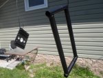
Functional Artist
Well-known member
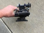
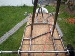
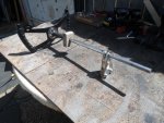
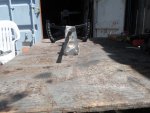
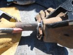
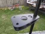
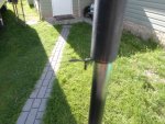
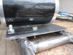
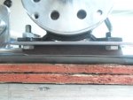
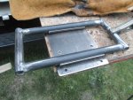
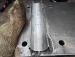
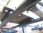
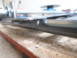
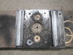
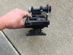
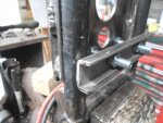
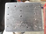
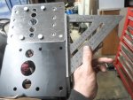
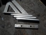
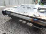
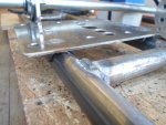
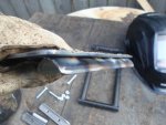
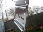
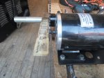
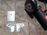
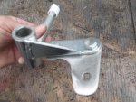
Cleaned 'em up a bit more 
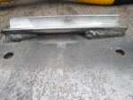
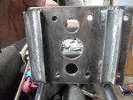
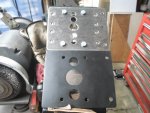
…then, "test fit" 'em
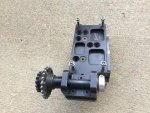
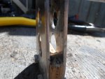
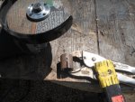
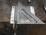
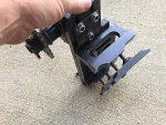
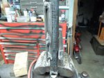
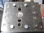
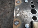
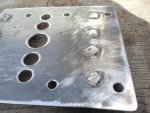
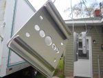
...& added the third hole
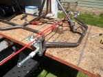
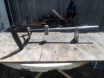
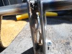
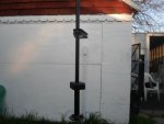
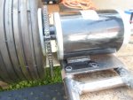
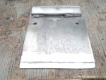
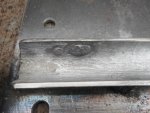
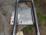
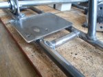
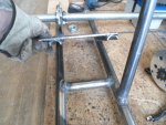
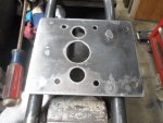
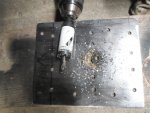
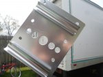
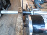
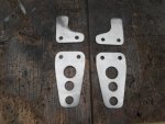
Used (2) 5/16" x 1" bolts to attach 'em
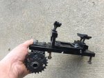
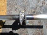
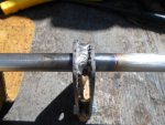
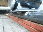
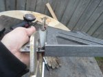
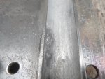
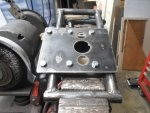
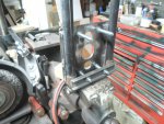
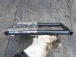
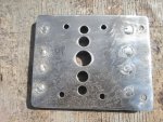
...but, they can easily be welded together too
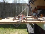
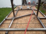
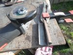
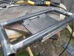
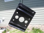
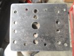
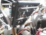
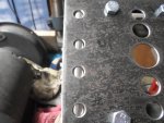
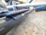
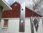
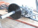
Super simple
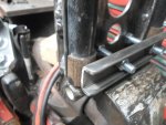
...but, still good-n-strong
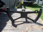
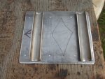
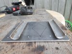
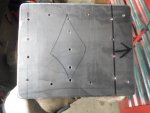
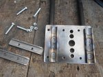
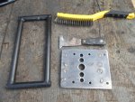
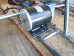
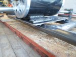
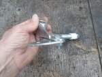
…then, "test fit" 'em
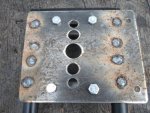
...& added the third hole
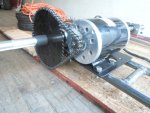
Used (2) 5/16" x 1" bolts to attach 'em
...but, they can easily be welded together too
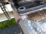
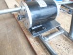
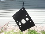
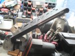
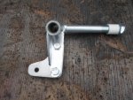
Super simple
...but, still good-n-strong
Attachments
-
 SAM_4073.JPG309.5 KB · Views: 11
 -
 SAM_4077.JPG310.6 KB · Views: 11
 -
 SAM_4080.JPG315.7 KB · Views: 10
 -
 SAM_4081.JPG314.9 KB · Views: 23
 -
 SAM_4082.JPG311 KB · Views: 11
 -
 SAM_4083.JPG313.3 KB · Views: 12