2017 - Shifter Kart - DNF

Status
Not open for further replies.

Ebrownie

Member
Messages
582
Reaction score
1
Location
Western Montana
Ok guys, here we go.

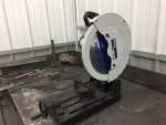
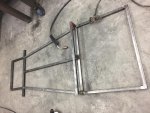
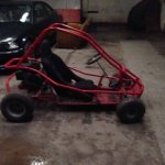
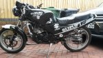
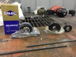
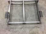
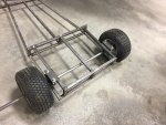
The plan is to build a one seater kart from scratch. This kart will see gravel road, dirt, and a little pavement. I will fabricate pretty much the whole thing. I don't have an engine for it yet, but it will be a dirt bike or four wheeler engine anywhere from 80 to 250cc. It will have 16x6.50x8 tires, live axle, and the frame will be 14ga 1x1 square tubing.

It's gonna be rough, and I'm gonna need some help. My goal is just to finish it and have a fairly solid machine in the end.:2guns:

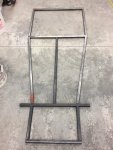
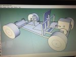
The second pic is the model I made of it in sketch up with all of the dimensions and measurements. The box in the back is where the engine will be.
 

Attachments

  • IMG_3887.jpg
    IMG_3887.jpg
    301 KB · Views: 15
  • IMG_3889.jpg
    IMG_3889.jpg
    663.1 KB · Views: 14

Ebrownie

Member
Messages
582
Reaction score
1
Location
Western Montana
So I started cutting up the tubing for my frame. Got the main structural framing cut to length. It's not welded yet, just put together how it's gonna be.

Btw, it's really nice to have a retired neighbor that has all the tools in the world that you can use anytime (for example, the metal chop saw pictured below!) :D
 

Attachments

  • IMG_3893.jpg
    IMG_3893.jpg
    232.6 KB · Views: 14
  • IMG_3892.jpg
    IMG_3892.jpg
    361.7 KB · Views: 9

Ebrownie

Member
Messages
582
Reaction score
1
Location
Western Montana
Started to weld up the frame with my buddy. After I got all the pieces cut out last week, I realized that I had a bunch of open ends on the tubing that I would have to put a plug in or close somehow. So instead, i cut the pieces at 45 degree angles so they fit together good. It shortened the frame by a couple inches, but it was probably too long anyways.

Second pic is one of my welds. Most Of them look about like that. I know it's not the greatest, but will hold together fine, won't it? The third pic is when I tried welding some scrap tubing together and hammering on it, and the tubing bent a lot before the weld broke.
 

Attachments

  • IMG_3898.jpg
    IMG_3898.jpg
    304.8 KB · Views: 24
  • IMG_3897.jpg
    IMG_3897.jpg
    162.2 KB · Views: 26
  • IMG_3899.jpg
    IMG_3899.jpg
    363.5 KB · Views: 12

totty921

2 stroke rippers
Messages
8
Reaction score
0
Location
uk
In process of building me self buddy kinda cheated abit tho using a murray hard drive frame snd droppin an rg125 gamma into it. Rear frame works near complete now..
 

Attachments

  • $_3-4.jpeg
    $_3-4.jpeg
    32.1 KB · Views: 7
  • 20170219_150936.jpg
    20170219_150936.jpg
    247.7 KB · Views: 5

Joe-405

Enjoying New Projects
Messages
2,673
Reaction score
69
Location
U.S.A.
Here I found a good pic of heat dissipation.
 

Attachments

  • c25-mig-weld.jpg
    c25-mig-weld.jpg
    85.9 KB · Views: 17

Ebrownie

Member
Messages
582
Reaction score
1
Location
Western Montana
It's been a while but I got an update for you guys. I'm still waiting on an engine, but it's looking like I might get it in a couple weeks. But my rear end stuff came in today; bearings, axle(not pictured), hubs, key stock, and lock collars. Hopefully I can get the back end put together by next weekend :thumbsup:
 

Attachments

  • IMG_3956.jpg
    IMG_3956.jpg
    313.4 KB · Views: 14

Flyinhillbilly

The great cornholio
Messages
2,468
Reaction score
81
Location
North West Arkansas
Here I found a good pic of heat dissipation.

That's a nice weld. For reference, what Joe is talking about here is the discolored area next to the weld. That's known as the heat affected zone, and you want some of that next to your weld, the way the weld looks doesn't matter nearly as much as the penetration (that's what she said) I've seen some ugly a$$ welds hold fine, and some fine examples of weld bead fail.
 

Ebrownie

Member
Messages
582
Reaction score
1
Location
Western Montana
I got a little work done tonight. My rear wheels have a super wierd bolt circle and bore diameters, so I am kind of making my own hubs. First, I used a 2 1/2" hole saw to cut out the inside of the hubs. I centered it by drilling it out while the hubs were bolted to the rims, which have a center hole of 2 1/2".

I bought some 1" bore 1/4" keyway weld-on sprocket hubs that have an OD of 2 1/2" inches. The plan is to weld the remaining hub plate to the sprocket hubs. I haven't welded them yet, just cut out the hubs. They seem like they will be pretty snug and centered. :thumbsup:
 

Attachments

  • IMG_3966.jpg
    IMG_3966.jpg
    242.7 KB · Views: 5
  • IMG_3965.jpg
    IMG_3965.jpg
    567.6 KB · Views: 4

Ebrownie

Member
Messages
582
Reaction score
1
Location
Western Montana
Finished up the rear hubs. I wire wheeled the paint off the plates, then centered and clamped everything together. Welded the hubs and plates together, and I think it will work out good. The hubs seem to be very centered in the rims.
 

Attachments

  • IMG_3996.jpg
    IMG_3996.jpg
    235.6 KB · Views: 7
  • IMG_3997.jpg
    IMG_3997.jpg
    231.9 KB · Views: 8
  • IMG_3998.jpg
    IMG_3998.jpg
    382.6 KB · Views: 6

pRoFiT

Can't buy it?, build it!
Messages
1,135
Reaction score
32
Location
California
Looks like they came out okay. Real test is to put some tires on them and give it a spin. Cross your fingers and hope for no wobble.

I tried the same on a disc brake...worst DIY i've done so far. ended up just buying a hub for the brakes instead. Some things you just want to do right, no matter the cost.
 

Ebrownie

Member
Messages
582
Reaction score
1
Location
Western Montana
Yes I know. The deal with these is I wanted to try to make these rims work because they were free. If it ends up wobbling, I will just bite the bullet and get new rear rims.
 

David Ham

Member
Messages
297
Reaction score
11
Location
Melbourne
I did the same thing, they ended up wobbling very slightly. You can just use washers on the bolts to fix it.
 

Ebrownie

Member
Messages
582
Reaction score
1
Location
Western Montana
Ok so I finally got my springs in so I started working on my rear bearing mounts. This kart is going to have 4-point mini suspension with coil springs. I got some 2x2 angle, drilled 2 bolt holes for the pillow blocks to mount to, and put the springs around the 1/2" bolts.

I am going to weld the angle to my frame. Right now the springs are a bit too long so when I cut them down, the bottom edge of the angle will sit flush with the piece of the frame I am welding it to. The plan is to also mount my brake caliper to the end of the bolts so my caliper will move with the bearings and therefore the rotor.
 

Attachments

  • IMG_4056.jpg
    IMG_4056.jpg
    508.1 KB · Views: 4
  • IMG_4057.jpg
    IMG_4057.jpg
    299.6 KB · Views: 8
  • IMG_4055.jpg
    IMG_4055.jpg
    281.4 KB · Views: 3

David Ham

Member
Messages
297
Reaction score
11
Location
Melbourne
Ok so I finally got my springs in so I started working on my rear bearing mounts. This kart is going to have 4-point mini suspension with coil springs. I got some 2x2 angle, drilled 2 bolt holes for the pillow blocks to mount to, and put the springs around the 1/2" bolts.

I am going to weld the angle to my frame. Right now the springs are a bit too long so when I cut them down, the bottom edge of the angle will sit flush with the piece of the frame I am welding it to. The plan is to also mount my brake caliper to the end of the bolts so my caliper will move with the bearings and therefore the rotor.

how are you going to keep those bolts rigid, so the axle doesn't move from side to side?
 

Ebrownie

Member
Messages
582
Reaction score
1
Location
Western Montana
6.5hp, the springs naturally resist the bolts tilting and since I won't be cornering at more than 20 mph, the side load shouldn't be enough to tilt the bolts. Even if it did, they only wiggle like 1/16" at most.

So, I welded up the angle to the frame and got everything mocked up with the springs and bearings.

I assembled it in a rather unconventional way. i don't have much room between the bearing and the bottom rail of the frame, as you can see in pic 5. So, let me explain the rather strange contraption in pic 2.

The nuts between the bolt heads and the top of the angle have been drilled out so they slide over the non threaded part of the bolt. They are essentially a spacer to move the bolt higher so the bearing fits over the lower frame tubing. It was easier than using 5 washers.

Then, the really short nuts between the bearing and the springs is a regular nut cut in half with a hacksaw. I did this so the bolt always moves with the bearing and slides through the angle, instead of vice versa. The reason I cut the nut in half is to maximize the spring length I could fit in there.

After I assembled it, I tested it out by stepping on it. It works pretty well. I might put nylon bushings or something (suggestions?) between the bolts and angle so it slides smoother. The only other thing is that I have a feeling the springs are going to be too weak. I suspected this, and it is not the end of the world to buy stiffer springs.
 

Attachments

  • IMG_4101.jpg
    IMG_4101.jpg
    301.3 KB · Views: 6
  • IMG_4102.jpg
    IMG_4102.jpg
    340.6 KB · Views: 3
  • IMG_4103.jpg
    IMG_4103.jpg
    367.7 KB · Views: 3
  • IMG_4105.jpg
    IMG_4105.jpg
    356.4 KB · Views: 8
  • IMG_4106.jpg
    IMG_4106.jpg
    264.4 KB · Views: 10
Status
Not open for further replies.
Top