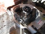
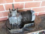
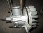
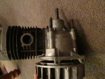
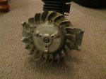
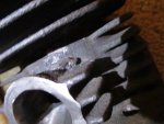
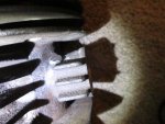
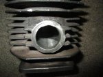
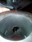
Yeah good stuff mate. To enlarge and raise The transfer ports on my Victa I got a small ball end carbide burr and a drill and attacked them from the top of the cylinder. I also deepened them and ground them down so that they transfer into the crankcase. I'll pull the cylinder off of mine tomorrow and take some pics and show you. Also, if you can, try and make sure that on your inlet, exhaust and transfers, that you try and make things smoother for the gas flow side of things, coz Sharp edges make for average flow and turbulence. In my engines I've done this as best I can and I'll show you that too. I'm no porting professional but what I've done is far better than how it left the factory. Lol.
---------- Post added 04-22-2017 at 12:04 AM ---------- Previous post was 04-21-2017 at 11:55 PM ----------
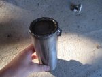
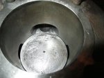
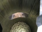
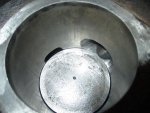
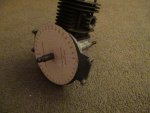
Oh yeah. Also, before you do any port work inside the cylinder, do your best to protect the cylinder walls from an excitably jumpy Skippy burr. They can something jump around away from where your working and you can accidentally Nick the bore which is **** thing. So to help protect the bore in case of this happening, I clean the bore from any oil, then run 3 or more layers of that fibrous 100 mile an hour tape. Cheep insurance ay!
 IMG_20170324_212601.jpg180.9 KB · Views: 7
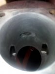 IMG_20170324_212636.jpg155.7 KB · Views: 8
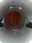 IMG_20170324_212748.jpg181 KB · Views: 8
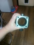 IMG_20170324_212821.jpg289.5 KB · Views: 8
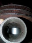 IMG_20170324_213125.jpg222.8 KB · Views: 8