Ah so just two..
great, both power up the HE Sensor wire so the internal Voltage regulator is
working properly on both, good.
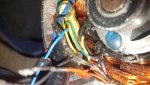
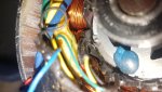
Motor 1 should be fine once it's got his end cap back,
I would've removed the rotor from the case entirely in order to prevent the magnets from getting harmed (they're quite brittle and thus crack easily if the rotor slams against them)
but if you remove it carefully now to check if all magnets are intact,
and when you put it back together
(also carefully to not whack the magnets when putting the rotor back in)
and put the cap back on I think it will be fully functional
I'm still baffled why you removed a sensor tbh..
but for sure that has to go back in of course

And if everything was done correctly it should be good.
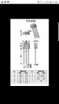
Post a pic of the removed HE Sensor please,
since curious minds and such;
I wonder if they're identical to my HE sensors in my totally and completely and utterly different BLDC motor... (I tell you why if they are
)
I still am sure that there is no need to replace them.
And the reason for that is that you are still impatient with this.
I asked you to measure, write down and show me the result,
for two reasons actually (Sorry.. for that
)
reason #1 which is important for the task at hand, was to see if the 5V PSU is working
properly
(since that powers the internal processor and if that's still working, chances are the microchip is still properly powered)
reason #2 was meaner I'm afraid
I wanted to see if you can follow that advice to test for your patience and precision.
and that unfortunately didn't turn out just as well.
You got the rough ida and jumped in an out as effortlessly as possible.
BUT: I need you to be my hands and eyes so to speak, and I'm still blind and in mittens
And in order to do things safely I
REALLY need to ask for more precision.
At one point I will likely ask to power that controller and probe for working voltages.
if you mess up by carelessly connecting wrong wires, you can blow the controller up,
and worse if you carelessly touch a high amp phase by accident you can get severly hurt.
(some amps through your chest can cause a severe heart attack)
I know it's tedious to take a pic of everyting you do or did
and that for a simple result like what I asked for now it's unlikely helpfull.
So to be sure and no matter how pointless it may sound,
when I ask you to "show me" a result,
I do not ask for just text but for a picture of whatever I asked you. (hands and
eyes )
and whenever possible a TRUE reading is what I ask for when I say "let me know" or "tell me"
(you highly unlikely got a 5V and 48V reading.. more likely a 5.1V and 49.7V or such)
So please, be precise and patient don't wing it and don't rush it.
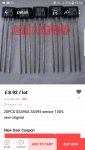
And just to get that out of the way.. the MosFets you attached are of no use for you,
you will not need them, and even if one day you need some THOSE are certainly incorrect!
wrong package, wrong voltage, and most likely everything else is also incorrect
So DO NOT buy!
[
EDIT]
So.. I checked and I never finished the remote reverse engineering for Oskar
So I don't have any pcb diagram for the controller,
which means there is no easy and gentle way for me to verify your controller is working properly.
We could check the gate transistors if you want, since they'd blow before the MosFets would,
but they're tucked away pretty tightly and them being SOT23 packages you'll need a terribly steady hand .. since the resistors are quite close and must not be shortened or you'll ruin the controller by testing
So I'd rather ask you to just show me the rear of your pcbs instead
a well lit sharp image of the Mosfet legs alone should tell us if one blew or not.
The PCB is conformally coated and that coat is heat sensitive..
a blown MosFet will cause the coating to turn yellow'ish brown usually
(often referred to as sh*tstains )
Far easier, far safer and almost as telling.
So a picture of each of your pcbs underside please!
I just assume at least one is unharmed and no ill discolouration is to be seen.
But in order to properly test I need a handfull of tools;
well you do..
you need two resistors one 10kOhm and one 1.8kOhm.
And about a foot of red (cut into three pieces) and about 4" of black wire
With that we will build ourself a sub 1V powersource by making a voltage divider to fake a HE signal
that we can feed into the motorcontroller to see if that triggers a static power on the phase wires.
I don't want to feed much more than what Kevin measured into the HE Sensors,
since I don't know how the signal is filtered and protected before it feeds into the microprocessor.
And burning the microprocessor is a bad idea
Idea is simple connect the lower value resistor to the black wire,
and the higher value resistor to one of the red wires,
exposing and tinning about 1/4-1/2" of the opposite ends
then solder the two open legs of the resistors and the remaining two red wires together
you should end up with something like that:

let me know when you're ready!
'sid


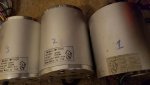
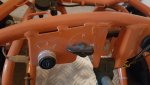
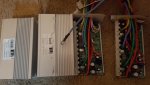
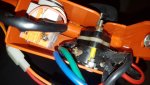

 these should work in all 3 motors?
 Thank you Sid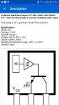
 ive come to far .... so I will buy off eBay can you give me the exact code of them and I will buy a mix of them different ohms thankyou Sid