Lunar Rover (prototype)

Functional Artist

Well-known member
Messages
5,629
Reaction score
3,264
Location
Toledo, Ohio
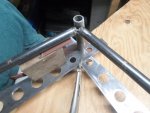
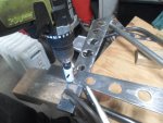
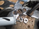
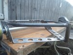
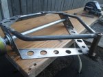
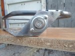
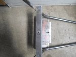
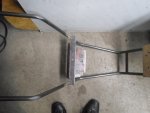
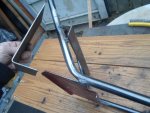
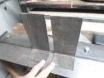
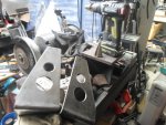
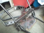
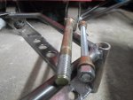
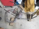
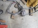
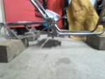
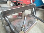
Made sure the "Goose Neck was centered & square
…then, marked the spot
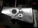
...drilled a pilot hole
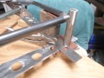
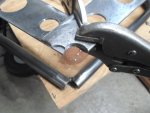
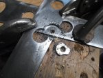
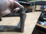
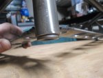
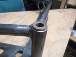
…then, used a hole saw (@ really low RPM's) :thumbsup: to cut-out the top layer
…& then, on thru the second layer :cheers2:

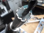
* Hole saw teeth still looks "like new" :2guns:

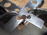
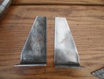
…& cut off the excess material :cool:
 

Attachments

  • SAM_1671.JPG
    SAM_1671.JPG
    310 KB · Views: 0
  • SAM_1670.JPG
    SAM_1670.JPG
    317.7 KB · Views: 0
  • SAM_1674.JPG
    SAM_1674.JPG
    312.9 KB · Views: 0
  • SAM_1675.JPG
    SAM_1675.JPG
    311.1 KB · Views: 0
  • SAM_1678.JPG
    SAM_1678.JPG
    309.9 KB · Views: 0
  • SAM_1694.JPG
    SAM_1694.JPG
    311.8 KB · Views: 0
  • SAM_1691.JPG
    SAM_1691.JPG
    315.2 KB · Views: 0
  • SAM_1692.JPG
    SAM_1692.JPG
    311.6 KB · Views: 0
  • SAM_1688.JPG
    SAM_1688.JPG
    316.1 KB · Views: 0
  • SAM_1686.JPG
    SAM_1686.JPG
    308.6 KB · Views: 0
Functional Artist

Well-known member
Messages
5,629
Reaction score
3,264
Location
Toledo, Ohio
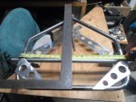
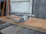
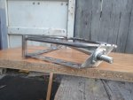
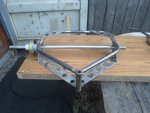
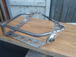
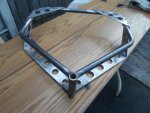
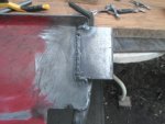
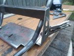
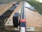
A little bit of grindin' & shapin' :thumbsup:
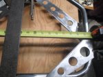
…some centerin' & levelin' :cheers2:
…& then, some weldin' :2guns:

Then, I re-installed the axle & bearings
...just to be sure :cool:

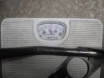
* Thinkin' about addin' some bracin' to the "goose Neck" area :idea2:
...but, so far, it only weighs ~7 lbs. :wai:
 

Attachments

  • SAM_1699.JPG
    SAM_1699.JPG
    314.3 KB · Views: 1
  • SAM_1698.JPG
    SAM_1698.JPG
    311.1 KB · Views: 0

  • SAM_1697.JPG
    SAM_1697.JPG
    316.1 KB · Views: 1
  • SAM_1696.JPG
    SAM_1696.JPG
    314.4 KB · Views: 1
  • SAM_1695.JPG
    SAM_1695.JPG
    312.9 KB · Views: 0
  • SAM_1701.JPG
    SAM_1701.JPG
    314.8 KB · Views: 2
  • SAM_1702.JPG
    SAM_1702.JPG
    310.9 KB · Views: 2
  • SAM_1703.JPG
    SAM_1703.JPG
    316.4 KB · Views: 3
  • SAM_1704.JPG
    SAM_1704.JPG
    315.5 KB · Views: 3
  • SAM_1717.JPG
    SAM_1717.JPG
    307.7 KB · Views: 1

itsid

Moderator
Staff member
Messages
11,563
Reaction score
247
Location
Ruhrpott [Germany]
I think I would've liked that better with a mitered cut and no overlap
(that way you also wouldn't have partially covered the last hole)

'sid
 

Functional Artist

Well-known member
Messages
5,629
Reaction score
3,264
Location
Toledo, Ohio
I think I would've liked that better with a mitered cut and no overlap
(that way you also wouldn't have partially covered the last hole)

'sid

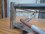
I figured overlapin' 'em would make for a stronger joint @ that 3-way connection :idea2:
...mainly cause their only 1/8" steel


I'm thinkin' the upper bar should transfer most of the forward thrust (applied by this axle anyways)
…but, there will still be "a lot" of "other" stress(es) applied to this junction :huh:

But, your probably right, a mitered cut woulda worked too :thumbsup:
 

Functional Artist

Well-known member
Messages
5,629
Reaction score
3,264
Location
Toledo, Ohio
It's been ~50* here lately :wai:
...business is kinda slow, 'cause of the holidays :huh:
…& the kids have been occupied with their "new" stuff :rolleyes:

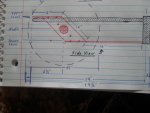
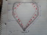
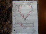
So, I've had some extra time to arrange my notes
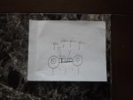
…& make a "proper" drawing :thumbsup:
 

Attachments

  • SAM_1730.JPG
    SAM_1730.JPG
    308.9 KB · Views: 5
  • SAM_1728.JPG
    SAM_1728.JPG
    310 KB · Views: 3
  • SAM_1726.JPG
    SAM_1726.JPG
    309.2 KB · Views: 4

Functional Artist

Well-known member
Messages
5,629
Reaction score
3,264
Location
Toledo, Ohio
This vehicle is mainly designed around the Cock Pit

Requirements:
...easy to enter & exit (space suit's are kinda bulky)
…& roomy (technical term) the (astro-) driver has to be able to move freely

Here's what I have in mind :thumbsup:
 

Attachments

  • SAM_1744.JPG
    SAM_1744.JPG
    301 KB · Views: 2
  • SAM_1749.JPG
    SAM_1749.JPG
    308 KB · Views: 3

Functional Artist

Well-known member
Messages
5,629
Reaction score
3,264
Location
Toledo, Ohio
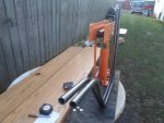
Pin Stripe Pipe

Before we move on let me show ya a few tricks that I learned, about shaping & bendin pipe :cheers2:

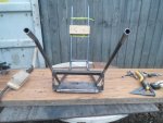
I had ta make (2) of those "Cock Pit" frame rails :thumbsup:
…& they need to be identical (or at least really close)

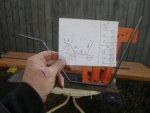
So, I started off with (2) pieces of (appropriate length) pipe.
…clamped 'em down (1 at a time) to a flat surface
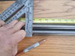
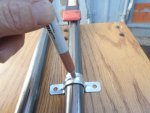
...& added a "pin stripe"

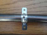
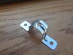
* To do so, I drilled a 1/8" hole into a 3/4" conduit clamp
…& used it as a guide to make a nice-n-centered straight line on the pipe(s) :2guns:

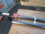
Then, clamped 'em down together (lined up nice-n-even)
…to measure & mark where the bend lines need to be
(used a square to make identical lines on both pipes, at the same time) :cool:
 

Attachments

  • SAM_1737.JPG
    SAM_1737.JPG
    312.7 KB · Views: 2
  • SAM_1735.JPG
    SAM_1735.JPG
    315.7 KB · Views: 2
  • SAM_1733.JPG
    SAM_1733.JPG
    315.2 KB · Views: 2
  • SAM_1732.JPG
    SAM_1732.JPG
    317.8 KB · Views: 2
  • SAM_1731.JPG
    SAM_1731.JPG
    312.4 KB · Views: 2
  • SAM_1743.JPG
    SAM_1743.JPG
    308 KB · Views: 2
  • SAM_1741.JPG
    SAM_1741.JPG
    310.2 KB · Views: 2
  • SAM_1739.JPG
    SAM_1739.JPG
    309.8 KB · Views: 2
  • SAM_1738.JPG
    SAM_1738.JPG
    310.1 KB · Views: 2

Functional Artist

Well-known member
Messages
5,629
Reaction score
3,264
Location
Toledo, Ohio
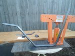
After markin' the pipe's, accordin' to the plan, I got the bender out
…& bent 'em up :thumbsup:

They look pretty darn close to me :2guns:
 

Attachments

  • SAM_1752.JPG
    SAM_1752.JPG
    310.3 KB · Views: 2
  • SAM_1751.JPG
    SAM_1751.JPG
    313.4 KB · Views: 1
  • SAM_1750.JPG
    SAM_1750.JPG
    315.1 KB · Views: 1
  • SAM_1744.JPG
    SAM_1744.JPG
    301 KB · Views: 1

Functional Artist

Well-known member
Messages
5,629
Reaction score
3,264
Location
Toledo, Ohio
This next part is kinda hard to explain :lolgoku:

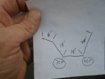
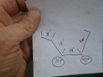
Front of Cock Pit (top & bottom) ~8" apart
Bottom (rear) ~12" apart
Rear (mid) ~17" apart
Rear (top) ~12" apart :huh:

Maybe some pics will help :thumbsup:

* I used some "spacer" boards (to help hold the front "pillars" evenly apart)
…then, after a lot of measurin' & double checkin', I used some conduit clamps (to "pin" the bottom rails down to a board) :2guns:
 

Attachments

  • SAM_1757.JPG
    SAM_1757.JPG
    309.9 KB · Views: 3
  • SAM_1758.JPG
    SAM_1758.JPG
    310.5 KB · Views: 3
  • SAM_1759.JPG
    SAM_1759.JPG
    315.3 KB · Views: 3

Functional Artist

Well-known member
Messages
5,629
Reaction score
3,264
Location
Toledo, Ohio
Tail 'er Hitch

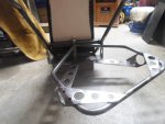
Next, we gotta connect the (2) frame rails :thumbsup:

A short piece of pipe will double as the lower, front, main frame "cross bar"
...& also a "thrust brace" for the rear of the battery box

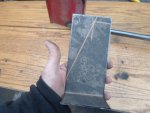
A piece of 1/8" plate will double as the lower rear main frame "cross bar"
(with a couple of structural bends already in it)
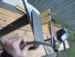
…& a piece of 1/8" angle iron will establish the upper connection point for the Tail 'er Hitch. :2guns:

* I usually try to avoid using angle iron
...but, this upper brace will encounter many dynamic stresses
(so, I figured a multi-dimensional piece was appropriate :cheers2:

* :idea2: Maybe we can "thoughtfully" hide it. :rolleyes:

** Looks kinda crooked in the pics
...but, I double checked, it's pretty square :lolgoku:
 

Attachments

  • SAM_1765.JPG
    SAM_1765.JPG
    309.1 KB · Views: 2
  • SAM_1764.JPG
    SAM_1764.JPG
    314.4 KB · Views: 2
  • SAM_1763.JPG
    SAM_1763.JPG
    307.3 KB · Views: 2
  • SAM_1762.JPG
    SAM_1762.JPG
    309.7 KB · Views: 2
  • SAM_1761.JPG
    SAM_1761.JPG
    311.9 KB · Views: 2
  • SAM_1766.JPG
    SAM_1766.JPG
    319.1 KB · Views: 1
  • SAM_1767.JPG
    SAM_1767.JPG
    311.9 KB · Views: 1

Functional Artist

Well-known member
Messages
5,629
Reaction score
3,264
Location
Toledo, Ohio
Attaching the Tail

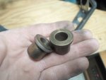
The Tail 'er will pivot on a 1/2" "pin" goin' thru (2) brass bushings :thumbsup:
…& mount in between the hitch brackets on the main frame :2guns:
 

Attachments

  • SAM_1720.JPG
    SAM_1720.JPG
    319.3 KB · Views: 3
  • SAM_1719.JPG
    SAM_1719.JPG
    314.1 KB · Views: 2
  • SAM_1718.JPG
    SAM_1718.JPG
    314.7 KB · Views: 2
  • SAM_1721.JPG
    SAM_1721.JPG
    312.9 KB · Views: 2

itsid

Moderator
Staff member
Messages
11,563
Reaction score
247
Location
Ruhrpott [Germany]
half inch Pin on a 13" lever?
with what? a 4" -6" height ??
If I interpret your drawing correctly, passenger weight is above and mostly behind the pin in question;
that seems sketchy

Any chance you can replace the brass bushings with slimline PTFE bushings and install a beefier pin (3/4" would be nice.. 5/8" may suffice... )

depending on the weight of your astronaut surrogate you should be aware of the torque involved..

essentially consider the passenger weight hanging on the axle
"swingarm" mounted by just the pin...
with say 220lbs of load that's ~240ft lbf
(plus whatever suspended weight the kart has)
spread over just the two bushings (spaced 4" or 6" apart means times three resp. two)
so we talk 480 to 720 ft lbf of lateral load on just a half inch through bolt, no?

Not sure, but a hefty bump in the road (like going down a curb or such) can already exceed the limits I guess...

'sid
 

Functional Artist

Well-known member
Messages
5,629
Reaction score
3,264
Location
Toledo, Ohio
half inch Pin on a 13" lever?
with what? a 4" -6" height ??
If I interpret your drawing correctly, passenger weight is above and mostly behind the pin in question;
that seems sketchy

Any chance you can replace the brass bushings with slimline PTFE bushings and install a beefier pin (3/4" would be nice.. 5/8" may suffice... )

depending on the weight of your astronaut surrogate you should be aware of the torque involved..

essentially consider the passenger weight hanging on the axle
"swingarm" mounted by just the pin...
with say 220lbs of load that's ~240ft lbf
(plus whatever suspended weight the kart has)
spread over just the two bushings (spaced 4" or 6" apart means times three resp. two)
so we talk 480 to 720 ft lbf of lateral load on just a half inch through bolt, no?

Not sure, but a hefty bump in the road (like going down a curb or such) can already exceed the limits I guess...

'sid

Very good observation, my friend :thumbsup:

I was (& still am) kinda concerned about this articulating joint as well
...but, I figured the weaker area would be where the upper Tail 'er Hitch mounts/attaches to the frame.

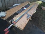
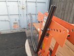
So, I kinda "boxed" 'em with some 1/8" steel "stress plates" :cheers2:

I'm gonna have ta think a bit, on the "pin"
...maybe we can "beef" 'er up :cheers2:

* The (astro) driver seat will be mounted to the lower frame rails
(just ahead of the pivot point) mainly to help keep the COG (center of gravity) low. :2guns:

Does that affect the equation (any)? :idea2:
 

Attachments

  • SAM_1785.JPG
    SAM_1785.JPG
    309.7 KB · Views: 1
  • SAM_1782.JPG
    SAM_1782.JPG
    314 KB · Views: 1
  • SAM_1780.JPG
    SAM_1780.JPG
    319 KB · Views: 1
  • SAM_1779.JPG
    SAM_1779.JPG
    312.2 KB · Views: 1
  • SAM_1823.JPG
    SAM_1823.JPG
    315.5 KB · Views: 2
  • SAM_1814.JPG
    SAM_1814.JPG
    317.7 KB · Views: 0
  • SAM_1811.JPG
    SAM_1811.JPG
    315.4 KB · Views: 0
  • SAM_1806.JPG
    SAM_1806.JPG
    307.4 KB · Views: 0
  • SAM_1795.JPG
    SAM_1795.JPG
    307 KB · Views: 0
  • SAM_1829.JPG
    SAM_1829.JPG
    317.7 KB · Views: 0
itsid

Moderator
Staff member
Messages
11,563
Reaction score
247
Location
Ruhrpott [Germany]
* The (astro) driver seat will be mounted to the lower frame rails
(just ahead of the pivot point) mainly to help keep the COG (center of gravity) low. :2guns:

Does that affect the equation (any)? :idea2:

not positively at least..
the kart is always suspended by the wheels,
so all weight between the axles means stress on the pivot bolt.

In fact the closer the mass is to the axles, the better,
the closer to the pivot the worse.
worst spot would be dead center between the axles.. maybe somewhat towards the hitch.

I mean sure, you can unload the hitch a bit by packing batteries and such behind the rear wheel .., but who would want that?

Let's hope for the best for now...
you might need to swap the pivot tube to a larger size in worst case..
and frankly.. swapping a tube, widening two drill holes...
I can't see how that would be a problem for you ;)

'sid
 

Functional Artist

Well-known member
Messages
5,629
Reaction score
3,264
Location
Toledo, Ohio
Pivot Pin Upgrade

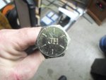
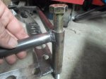
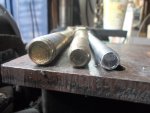
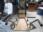
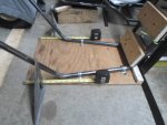
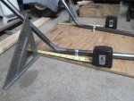
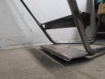
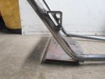
Thank you sir :thumbsup: I've taken your advise & upgraded the pivot pin to a 3/4" grade 8 bolt :cheers2:

* The "action" of the pivot seems even smoother now :2guns:
 

Attachments

  • SAM_1903.JPG
    SAM_1903.JPG
    314.3 KB · Views: 0
  • SAM_1894.JPG
    SAM_1894.JPG
    313.8 KB · Views: 0
  • SAM_1886.JPG
    SAM_1886.JPG
    314.3 KB · Views: 0
  • SAM_1890.JPG
    SAM_1890.JPG
    314.4 KB · Views: 0
  • SAM_1878.JPG
    SAM_1878.JPG
    318 KB · Views: 0
  • SAM_1920.JPG
    SAM_1920.JPG
    310 KB · Views: 2
  • SAM_1919.JPG
    SAM_1919.JPG
    309.8 KB · Views: 1
  • SAM_1916.JPG
    SAM_1916.JPG
    314.5 KB · Views: 2
  • SAM_1905.JPG
    SAM_1905.JPG
    324 KB · Views: 0
JTSpeedDemon

2019 Build Off Winner!
Messages
4,026
Reaction score
162
Location
Texas
Investing in Grade 8 hardware really does save headaches down the road. I can happily say that from experience! :lolgoku:
 

Functional Artist

Well-known member
Messages
5,629
Reaction score
3,264
Location
Toledo, Ohio
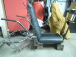
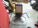
Here's about how it'll look with the seat in place :thumbsup:
 

Attachments

  • SAM_1907.JPG
    SAM_1907.JPG
    319 KB · Views: 1
  • SAM_1908.JPG
    SAM_1908.JPG
    314.7 KB · Views: 1
  • SAM_1912.JPG
    SAM_1912.JPG
    322.3 KB · Views: 1
  • SAM_1914.JPG
    SAM_1914.JPG
    312.9 KB · Views: 1

Functional Artist

Well-known member
Messages
5,629
Reaction score
3,264
Location
Toledo, Ohio
The Nose Section

Next in line, (just ahead of the Cock Pit) would be the battery box, :thumbsup:

The batteries will be
...oriented sideways
...lined up in a row
…& slung way down low :cheers2:

And finally, the front axle which is to be located just ahead of the battery box
…with some "foot pads/floor boards" on each side of the battery box & sprocket area :2guns:

* There will be a protective "cage" around this sprocket & rotating shaft. :cool:
 

Attachments

  • SAM_1873.JPG
    SAM_1873.JPG
    312.1 KB · Views: 3

Functional Artist

Well-known member
Messages
5,629
Reaction score
3,264
Location
Toledo, Ohio
Concept re-evaluation

not positively at least..
the kart is always suspended by the wheels,
so all weight between the axles means stress on the pivot bolt.

In fact the closer the mass is to the axles, the better,
the closer to the pivot the worse.
worst spot would be dead center between the axles.. maybe somewhat towards the hitch.

I mean sure, you can unload the hitch a bit by packing batteries and such behind the rear wheel .., but who would want that?

Let's hope for the best for now...
you might need to swap the pivot tube to a larger size in worst case..
and frankly.. swapping a tube, widening two drill holes...
I can't see how that would be a problem for you ;)

'sid

This still concerned me :huh:

So, I've done a complete concept re-evaluation :thumbsup:
…& some more research too :cheers2:

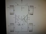
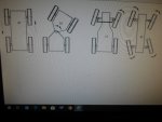
It seems that most articulating vehicles are set up with the "tractor" or power unit "balanced" over (1) axle
…& the "pay load" or bed/bucket pretty much over the other one

But, that's NOT how "most" go karts are designed :ack2:
…& NOT quite what I have in mind :mad:

The largest mass (heaviest thing) supported between the axles on an electric kart is the driver (usually ~150-200 lbs.)
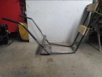
...then, the battery pack (~40 lbs.)
…then, the motors (~10 lbs. ea.)
…& then the frame (but, its weight is kinda spread out)
(the weight of the axles, wheels & tires are "actually" supported by the ground)

So, we can "balance" the weight of the motors mostly over the axles
…& move the batteries around a bit
...but, that driver????????????
...it seems like it's best to keep 'em low & mostly in the middle :rolleyes:

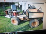
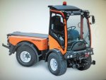
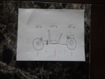
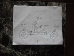
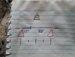
* I kinda like the concept in the (6th) pic
...but, I don't think our (astro) drivers legs will bend like that :smiley_omg:

Well, after extensive evaluation, (I've thought this thru 100's of different ways)
I think I've got it Overcompensation
...maybe we'll upgrade to a 3/4" x 36" pivot pin, on that ~13" lever :2guns:

How does that effect the equation? :cool:
 

Attachments

  • SAM_1926.JPG
    SAM_1926.JPG
    311.4 KB · Views: 1
  • SAM_1928.JPG
    SAM_1928.JPG
    311.7 KB · Views: 2
  • SAM_1925.JPG
    SAM_1925.JPG
    315.8 KB · Views: 2
  • SAM_1938.JPG
    SAM_1938.JPG
    309.4 KB · Views: 1
  • SAM_1923.JPG
    SAM_1923.JPG
    310.2 KB · Views: 3
  • SAM_1922.JPG
    SAM_1922.JPG
    316.8 KB · Views: 4
  • SAM_1940.JPG
    SAM_1940.JPG
    315.3 KB · Views: 3
  • SAM_1933.JPG
    SAM_1933.JPG
    305.9 KB · Views: 3
  • SAM_1931.JPG
    SAM_1931.JPG
    311.3 KB · Views: 3
  • SAM_1924.JPG
    SAM_1924.JPG
    312.6 KB · Views: 5
Top