Ongoing Dingo 285 build help / questions

Status
Not open for further replies.

drecon

New member
Messages
71
Reaction score
4
Location
KCMO
On going Dingo 285 build help / questions

ok guys, I'm starting to tinker with putting things back together on the Manco Dingo 285. I started this thread to house all my random questions as I go through this so as to stop cluttering up the forum with 15 different threads. Please check back often to see what I need help with! :surrender:

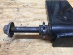
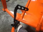
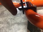
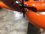
First up, from what I can tell this cart is a pre 1995. Tonight I went and got replacement shoulder bolts for the brake and throttle pedal pivots. I matched up the old size for new. Now when I put it all back together its all really loose and sloppy. I didn't notice it being that way when I took it apart but it was also still covered in years of dirt and grime. Anyway, the pedal stop brackets have a rather large range of motion being as they are bolted on with only one bolt each, so they rattle and flop around. Is this normal? Am I missing something here?
 

Attachments

  • IMG_4875.jpg
    IMG_4875.jpg
    421.8 KB · Views: 12
  • IMG_4876.jpg
    IMG_4876.jpg
    249.9 KB · Views: 14
  • IMG_4877.jpg
    IMG_4877.jpg
    177.5 KB · Views: 13
  • IMG_4878.jpg
    IMG_4878.jpg
    184.4 KB · Views: 13

drecon

New member
Messages
71
Reaction score
4
Location
KCMO
Ok question two, are the 1"ID 2"OD bearings used in these mango rear axles not a common size? Ive been to 3 places local so far, two did not have the correct bearings. One had what I thought was correct until I got it home. It has some weird little metal stud on the outer bearing surface that I don't understand. It would fit inside the new flanges fine if not for this little nub. Is it supposed to be like this?? The flanges match the old ones exactly and the old bearing sits inside of the new flanges just fine. Nice and flush all the way around. The new bearing won't fit either set of flanges because of that nub.
 

Attachments

  • IMG_4884.jpg
    IMG_4884.jpg
    216 KB · Views: 5
  • IMG_4882.jpg
    IMG_4882.jpg
    180.4 KB · Views: 4
  • IMG_4881.jpg
    IMG_4881.jpg
    194.3 KB · Views: 3
  • IMG_4880.jpg
    IMG_4880.jpg
    350.9 KB · Views: 3

drecon

New member
Messages
71
Reaction score
4
Location
KCMO
Number three, can this throttle cable casing be cut down and have the end put back on? Is this something anyone can do or does it require special tools to remove and put back on? The throttle cable that came on this cart is in ok shape but its really long, like 74" long inner wire and 71" jacket. I played with different routing options and all leave a pretty large loop of cable somewhere which seems like it will got caught on something eventually..
 

Attachments

  • IMG_4885.jpg
    IMG_4885.jpg
    249.6 KB · Views: 6

Whitetrashrocker

Inmate #952016
Messages
4,608
Reaction score
3,639
Location
Southern New Mexico
And the pedals on my Dingos are sloppy too. This isn't a precision machine....
I put a washer between the tubing and the pedal. It helped with the wibble wobble in the pedal.

---------- Post added at 09:06 PM ---------- Previous post was at 09:04 PM ----------

Try to untwist the end of that cable off.
 

KartFab

Active member
Messages
3,381
Reaction score
54
Location
Dallas, TX
1) pedals are installed backwards
2) pedals are missing return springs
3) throttle cable housing and cable can be shortened but you shouldn't. Zip ties keep things out of the way.

Throttle pedal https://kartfab.com/go-kart-plans/go-kart-throttle-cable
Brake pedal https://kartfab.com/go-kart-plans/go-kart-brake-band

Different kart but same manco pedal setup.

If you are set on shortening the cable and housing
1) housing end has dimple on it to keep it stuck to the cable housing. Drill out the dimple with a small drill bit and it will slide off.
2) cut housing with an abrasive cut off wheel. You may need to file off burrs on the inside edge
3) reinstall housing end, and use a small awl or punch to make a new dimple to get it to stay on the cable housing end
4) soldering the cable where you want to cut it will keep it from fraying.
 

Attachments

  • IMG_0133.JPG
    IMG_0133.JPG
    261.1 KB · Views: 0

drecon

New member
Messages
71
Reaction score
4
Location
KCMO
I've had the pedals on both ways. I'd read on this forum they could be turned around in an attempt to shorten the reach from the seat. My 9yr old is on the small side so we were trying to determine what would be the best fit to help him reach.

I don't have the return springs. Kartfab, every time I've seen those springs they are mounted like in your link, with round stock for the pedal stops. Will those particular springs fit and work with my style of pedal stops?? If so I'll order a set. I do have a washer in between which helps a little but still sloppy. Two washers is too thick and won't fit properly. I've noticed on the latter dingo's they ditched the separate pieces and went to welded to the frame. Wish I'd thought of that when the frame repairs were being done and I would have welded them down.

In regards to the bearing I dunno. Seems like its there on purpose?? I can just take it back and get my $6 back and not deal with it, but I also can't seem to come up with the proper bearing local. I may do that though and just add one to my list for gopowersports.

I'm guessing the throttle cable was changed to this long one when the motor was replaced as I don't think the original motor had the throttle setup on the right hand side like this one does. When I got it was routed from the pedal across the floor pan and up and around the seat and then back to the right hand side in front of the motor and then up the cage and to the linkage. It just looks really sloppy with all the extra cable. The problem with shortening it and trying to run it down only the right hand side is making the loop back to the linkage would be too tight of a turn if I followed the advise I was given to attach it to the throttle lever instead of attaching it to the governor arm. The previous owner had it attached to the gov arm.
 

Hellion

Moderator
Messages
8,454
Reaction score
3,575
You can very well shorten throttle and brake cables, and you should if it is needed. We, those in the hobby, do it all the time. I don't get this "shouldn't" business.

If you want to get real creative with the small rider/pedals-too-far-away issue, you could easily fashion some pedal blocks made out of wood, etc., and at the proper thickness. Add some anti-slip material to the contact surfaces and you're good to go. Temporary use only and uses the existing holes in the pedals for the securing bolts. Sounds like a good place for wing nuts...

Grind the nubs off.


Where did you find the replacement shoulder bolts, what are the specs and the stock number if any?
 

mckutzy

Well-known member
Messages
8,353
Reaction score
107
Location
bc, canada
Those bearing are the same as any the others...some manufactures put the nub in there so it won't rotate in a pillowblock housing...
I had to grind off a hundred of those little nubs for some custom bearing housings once... What a pain.. Boss forgot to say no nubs to the bearing guy...
 

drecon

New member
Messages
71
Reaction score
4
Location
KCMO
Hellion,

The shoulder bolts are just from the local true value hardware store here in town. No part or supplier numbers as I didn't write them down. They are 3/8" socket head, 1 1/4" shoulder shaft, 1/2" of thread, width of head is 1/4" for a total of 2" overall length. They matched right up to the old ones other than the old were hex head instead of socket. The next size down reduced the shoulder shaft 1/4" and would be too short to make it all the way through the frame tube.

I also went ahead and modified the throttle cable. I did just as KartFab directed, drilled out both dimples on the cable end piece cut the cable and reinstalled only instead of redimpling the end piece I heated up the drilled out holes with a soldering iron and used just a small little drop of solder in each one to secure the end. Worked perfectly! I put some pics in my build thread.

Now for my next question, does anyone know of a source of a steering wheel adapter that can be bolted onto the 3/4" O.D. steering shaft? Since it's already been power coated I don't want to weld. So I need to find a bolt on adapter that will let me use a standard 3 bolt steering wheel. The holes in both the plastic stock steering wheel and the shaft are wallered out a bit and makes the steering wheel real sloppy. I'd like to stiffen that up. Plus the old wheel is pretty rough looking and weathered.

In regards to the bearing, I'm going to take you guys' advise and just grind the nub off!
 

drecon

New member
Messages
71
Reaction score
4
Location
KCMO
lol I haven't gotten to the bearing yet, but its stilll on my list.

Ran into more issues today. A rather frustrating one to be honest. My throttle is not working. I am going to make a separate thread on this one in the engine forum to get some more views.
 

drecon

New member
Messages
71
Reaction score
4
Location
KCMO
Well I got the nub ground off the new bearing and started the test fit of the rear axle. Ran into a surprise. Now keep in mind the left hand wheel could not be removed. At. All. Seriously. Also keep in mind at some point a prior owner spot welded the brake drum to the axle. With that being said I did not change anything on the axle as far as spacing of the left wheel, brake hub, sprocket. Nothing was changed on the jackshaft plate either as far as how the shaft, sprocket and spacers were placed. No changes were made to the jackshaft mounting holes or the engine mount holes.

So I slid the axle in and attached it to the frame on the left side and installed the new bearing on the right side. The sprocket lined up just like it did in regards to the sprocket guard. But now for some reason with the jackshaft in place and bolted down to the frame on the motor mount and with the motor in place, the jackshaft sprocket does NOT line up with the axle sprocket..?? :huh: 
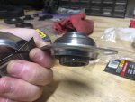
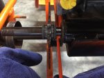
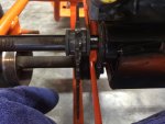
This isn't adding up, now I have a 9/16" gap. First thought is no biggie I'll just add a spacer. Problem with that is I'm afraid if I do that a new driven unit won't line up on the jackshaft properly. I dunno what happened, but if I set it up this way the sprockets won't even come close to lining up! The only thing I can think of is that the only thing holding the jackshaft sprocket in place was its key. But I wouldn't think that would've held would it??

The first pic shows the jackshaft plate alignment as it was before I cleaned it all up. The other pics show how it is now.
 

Attachments

  • IMG_4853.jpg
    IMG_4853.jpg
    294 KB · Views: 14
  • IMG_4937.jpg
    IMG_4937.jpg
    291.2 KB · Views: 13
  • IMG_4936.jpg
    IMG_4936.jpg
    240 KB · Views: 10
  • IMG_4938.jpg
    IMG_4938.jpg
    221.7 KB · Views: 13

Hellion

Moderator
Messages
8,454
Reaction score
3,575
You don't remember how it looked and the way all the geometry fit together before you disassembled it? Uh oh, should have taken a photo. :D

It had to have worked at one time.


#133 are spacers, for instance:

Part #1119 SPACER .625 ID 1.062 OD .125 THK Z
 

Attachments

  • TAV breakdown.jpg
    TAV breakdown.jpg
    54.7 KB · Views: 5

drecon

New member
Messages
71
Reaction score
4
Location
KCMO
Yup that first pic is my reference pic and exactly how that was when I tore it down, the only thing removed was the TC sheave. I had taken it (and it alone) off previously to get a better look at it. I put the washer and lock nut right back on the shaft and that's how it was left until I removed the engine and plate. That's what I don't understand..

The jackshaft plate just has holes not slots so it can't be mounted to the engine any differently than it was. The engine mount has slots but they run forward and backward not left and right, so it cant be shifted either.
 
Status
Not open for further replies.
Top