LeeMajors
New member
Hi Lee.
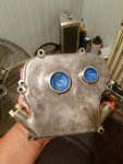
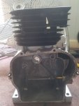
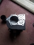
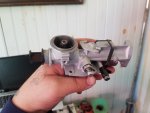
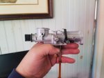
I ran into the same issue of how to plug the hole for the governor crank (as it is called). Read that some do utilize the crank rod or use JB Weld or some High Temp RTV sealant either alone or in conjunction with the rod to plug the hole.
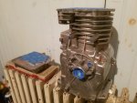
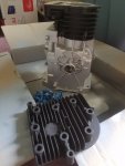
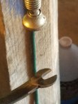
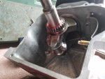
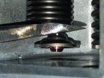
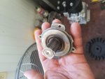
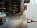
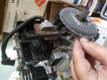
I decided to tap the hole for a 1/4" machine screw and sealed the threads with Permatex High Temperature Thread Sealant. Says it's resistant to 400°F. Some of it oozed out around the flat washer I used--it's the white substance. The screw is only 1 1/4" LOA so it doesn't protrude into the crankcase.
I used a 1/4 NC20 tap.
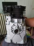
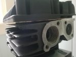
Thx for this man ^^^ I was considering tapping it also and after seeing yours I just might go that route? It just looks so much cleaner that way. Great job on that, it looks amazing! Just out of curiosity; did you paint that yourself and if so what type of paint is that? It looks REALLY good man! I finished painting/curing mine a few days ago and just haven't had a chance to UL the pics. Anyway, Thank you again for the pics and the reply, you really just helped me make my decision.