Silvergrizz
New member
Bob,
A word to the wise, ...
Be very, very careful welding those 68* pieces, ... They move, ... a lot. Go very, very sloooooo.
I did, as per your suggestion. It was along day today. I tack welded 1/4 in at a time to keep things from moving.
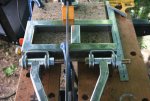
OH, ... I almost forgot to tell you, .. when welding the suspension block, ... on the open end, (rear of the block) tack weld a piece to keep them from closing in on you. They start bending right in the steering rack cross member piece.
I clamped a spacer about 2/3 of the way back just to prevent that, seems to have worked out OK.
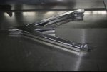
The A-arms are all welded up and the suspension block is about half done. Taking the slow and easy path here also.
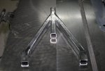
I sanded down one of the A-Arms to check for warp-age. After sanding, I laid it out on the table saw, which is a nice flat surface, and
 Flat as a pancake. It's been a good day. Attached are a couple of pictures of the finished A-arm, just have to weld the heim joint nut in tomorrow.
Attachments
-
 IMG_3203R.jpg62 KB · Views: 132
 -
 IMG_3204R.jpg68.2 KB · Views: 130

 Since this is my first crack at this, am I missing anything here? :toetap05:


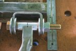
 I've been studying that last picture and I realized I could gain .30 of an inch just by removing the back washer and moving the inside back washer to the other inside. Those washers are .15" thick each. If I offset the bracket by another
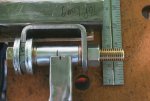
 :toetap05:
