
 |
Fig. 1 |
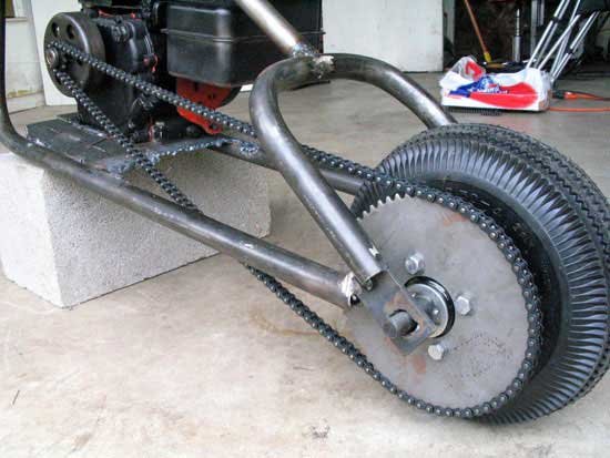 |
Fig. 2 |
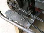 |
Fig. 3 |
 |
Fig. 4 |
 |
Fig. 5 |
 |
Fig. 6 |
Chop That Frame Up!
How to Build a Mini Chopper Frame and Schematics
The frame design is one of the most rewarding parts of building a mini chopper, so if you are able, we strongly suggest building your frame rather than buying one. However, you must be sure of your welding ability. Either you, or someone you love will be supported by it, and traveling fast — you do not want this thing to fall apart.
Thinking About Frame Design
The first thing to do when considering the frame is what you want it to look like. If you
haven't already discovered it, there are many different styles of frame design, and subtle nuances to each. Surf our photos and others, and print a few out. This will help you sketch your own ideas better.
Using a Bender For the Frame Design
There are two main ways you can make your frame — with or without a bender. A frame that is square rather than rounded simply will not look as good. Our frame was made from 3/4" pipe, bent with a Harbor Freight hydraulic pipe bender.
[Learn about bending and selecting material].
How We Built the Frame
First, we cut and bent two sections of pipe to the same bend, roughly 100 to 110*. It's not too time consuming to bend them equally in the pipe bender, though it's not an exact science. We've heard that if you count the pumps you can make the same bend twice, so you may try that method.
Then we made two 90* pieces of material for the rear wheel assembly. Since the pipe bender won't make a 180* bend, you must make two pieces and then weld them together in the "U" shape. This "U" should be longer than necessary so you can cut the material to length when you mock it up.
The backbone tube was then welded to the "U" assembly. This will need to be very square. To accomplish this we laid the assembly on the concrete and traced the "U" shape. Using a carpenter's square we drew two parralell lines toward the backbone. Then we drew a 90* line through the two lines. From this line we were able to draw squared lines that outlined where the backbone was to be attached.
You must fishmouth the joint between the "U" and backbone. This can be done with a grinder.
Assembling the Upper and Lower Parts of the Frame
Take the two pieces making the lower assembly, and lay on the concrete. Take your upper assembly and mock up how you'll like the stretch of the frame to look. Since you cut all the materials longer than needed, you'll have some options.
Fabricate the Engine Mount
You can read more about these options in the parts section.
Engine mount was custom sized for the frame from a purchased engine mounting plate and 1/4" flat stock welded to form the correct size. When welding long welds like these, ensure that you tack first and use lots of short welds so you don't warp the plate or frame.
You can make your own mounting plate, but it's often cheaper to buy them, and you won't need cut the slots for the mounts.
Position The Engine
When designing your frame, consider where your engine will fit. You'll want the engine to be close to the rear wheel to minimize chain length and position the clutch farther from your legs.
Tack the plate in to your frame and place your engine on it, noting the adjustment travel, exhaust and carburetor clearances