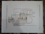
Whelp, I can't figure it out. The current flow just doesn't make sense to me. I'm pretty sure I'm going to be ok once I get the right signals coming out of the contactor, but until then, I'm stumped. I've read through FAs posts several times and reviewed the kelly controls diagrams, but I still don't understand. Mainly, it's the black dots on the wiring diagram that are most confusing. So basically, I read the following post:
http://www.diygokarts.com/vb/showthread.php?t=40937&highlight=contactor
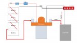
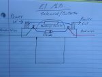
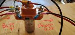
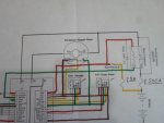
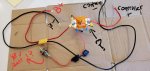
And I've achieved the picture below. I'm not sure how to wire the switch so it energizes the contactor? Where does the "A2" post go to on the contactor? Maybe I've got it backwards. Also, I think I need to put that 4amp fuse on the other side of the switch so it is stepped down right off the battery. Can I connect a 48volt battery to the switch? If not, how to I wire up a 12volt source from 4 12volt batteries wired in series? Sorry about all the questions...i'm scratching my head. Shout out to FA for all the videos and posts! Very helpful.
http://www.diygokarts.com/vb/showthread.php?t=40937&highlight=contactor
And I've achieved the picture below. I'm not sure how to wire the switch so it energizes the contactor? Where does the "A2" post go to on the contactor? Maybe I've got it backwards. Also, I think I need to put that 4amp fuse on the other side of the switch so it is stepped down right off the battery. Can I connect a 48volt battery to the switch? If not, how to I wire up a 12volt source from 4 12volt batteries wired in series? Sorry about all the questions...i'm scratching my head. Shout out to FA for all the videos and posts! Very helpful.
Attachments
-
 20200301_153501.jpg192.8 KB · Views: 19