Hello forum members,
I am deciding whether a diode/capacitor CW circuit,or a hand-wound step-up transformer is easier,and more practical; I am only needing at most a voltage multiplier(I am aimimg for 36 volt from a 12 volt AGM design strategy!) for my electric pmdc powered bike trailer with dual curry brushed motors-I have magnet wire,T200 toroid,fiberglass tape,some electrolytic caps, hi amp diodes so either way it would be practical to make a decent working voltage multiplier!
I basically want to know which "vm" circuits that the members have used with good results, and what circuit is more efficient/practical??
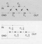
btw,I have uploaded a few examples of voltage multiplier circuits similar to what I will like to try,although the transformer core I will be using is a toroid design,and not a split-bobbin/E core design-I am probably going with the diy hand wound stepup power transformer since it will most likely be able to handle the high amperes that the 2 Curry PMDC motors will require!!!!!
Thanks in advance for a reply!
I am deciding whether a diode/capacitor CW circuit,or a hand-wound step-up transformer is easier,and more practical; I am only needing at most a voltage multiplier(I am aimimg for 36 volt from a 12 volt AGM design strategy!) for my electric pmdc powered bike trailer with dual curry brushed motors-I have magnet wire,T200 toroid,fiberglass tape,some electrolytic caps, hi amp diodes so either way it would be practical to make a decent working voltage multiplier!
I basically want to know which "vm" circuits that the members have used with good results, and what circuit is more efficient/practical??
btw,I have uploaded a few examples of voltage multiplier circuits similar to what I will like to try,although the transformer core I will be using is a toroid design,and not a split-bobbin/E core design-I am probably going with the diy hand wound stepup power transformer since it will most likely be able to handle the high amperes that the 2 Curry PMDC motors will require!!!!!
Thanks in advance for a reply!
Attachments
-
 comp2.gif15.4 KB · Views: 1
 -
 step_up_transformer.gif30.6 KB · Views: 3
 -
 comp1.jpg18.5 KB · Views: 2
Last edited: