What's with this steering set-up? Help please!

Status
Not open for further replies.

SirLancelot

New member
Messages
4
Reaction score
0
Hello folks,
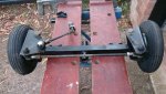
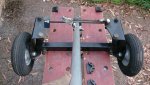
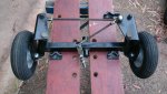
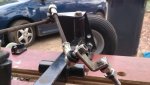
I'm making a go-kart for my 11 year old and I'm using the steering from an old mobility scooter. I'm having trouble working out this steering system though. I never saw the scooter so i don't know why it's set up like this. (See photos)

Could you take a look at these photos and help me understand how/if i can use it for go-kart steering? Three main questions but any advice would be appreciated, I'm an absolute novice!

1) I obviously want to mount the steering column along the centre of the go-kart but to do this the tie rod will have to be in a strange position. Won't this affect how it steers?

2) Why is the tie-rod so long? I guess i could cut some of the bolt and make it shorter but before i do anything drastic I wanted to know why it was so long in the first place!

3) Would it bolt onto a steering column in a direct North-South / 0º-180º alignment? I ask because when the wheels are straight, I thought maybe the tie-rod would need to be pointing 340º (i.e. left of straight ahead) or will this single tie rod, off-centre set up affect the steering?
DSC_0004.jpg

DSC_0003.jpg

DSC_0002.jpg

Thanks for reading, please let me know your thoughts!
 

Joe-405

Enjoying New Projects
Messages
2,673
Reaction score
97
Location
U.S.A.
There isn't anything wrong with that setup. It's like a old gasser drag car straight axle setup. Just use a regular steering column with only the short tie rod attached to the turning arm and it will work just fine.
 

SirLancelot

New member
Messages
4
Reaction score
0
Thanks Joe-405, reassuring to know i can keep going with this now!

pitman arm.jpg

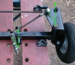
I still reckon I'll need to make sure the turning arm (i think that's what it's called-lower left corner) is at the same angle as the joint where the tie-rod is attached (the shiny ball&socket joint in the photo where the paint has come off).
Otherwise it'll be easier to turn left than right won't it?

Tried to show it with the green lines in the above photo.
 
Last edited:

ezcome-ezgo

G'me sumthin to write on
Messages
5,948
Reaction score
2,926
Location
Atlanta, GA
It wouldn't hurt, just so you have a full range of motion in both directions. That angle BTW is where ackermann lives. Look him up.
 

itsid

Moderator
Staff member
Messages
11,563
Reaction score
246
Location
Ruhrpott [Germany]
The mobility scooter has a trailing setup not a leading setup..
(so passenger view would be the third pic!)

it's a very short vehicle with a perfectly upright steering stem;
the thing dangling from the control tierod is already the pitman arm.

So as it was on the mob.scooter the two tierods were perfectly parallel;
the pitman arm thingy pointing forward.. and that bolt then directly mounts to a steering stem.
sitting inbetween the tie rods and the actual axle beam pointing straight up.

'sid
 

SirLancelot

New member
Messages
4
Reaction score
0
Thanks sid!

I'm disappointed by my mistake: I thought that it must have been leading setup because the Ackermann angle would then be pointing towards the centre of the rear axle.
Also I assumed it because this would mean the centre of the front wheel's axle would lie behind the yoke, making an effective Camber that would self-centre the wheel better.

Stupid question:
If i just made this a leading setup, would there be devastating negative effects?
 

itsid

Moderator
Staff member
Messages
11,563
Reaction score
246
Location
Ruhrpott [Germany]
Very valid points..
I was wrong!

I was going by your second pic (the wheel sitting in front of the actual kingpin then) assuming it'd effectively generates a positive caster angle.
Not thinking about the kingpin itself sitting straight in that direction making it in fact a negative caster..

It shouldn't make a structural difference though,
and if leadings works out to be the better geometry, then so be it. [even IF it was a trailing setup originally] :D

'sid
 

SirLancelot

New member
Messages
4
Reaction score
0
No worries sid. It's good that your reply got me thinking a bit more about Ackermann/Pitman/leading/trailing etc!

I have now added an aluminium steering shaft.

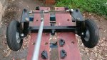
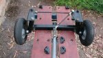
So if I was to using this steering as a leading setup, the single tie rod would presumably be too long for a centred steering shaft, so which of these following options would you folks go for and why? (Please don't say the 1st one, i wanted symmetry!)

DSC_0007.jpg

DSC_0008.jpg

DSC_0009.jpg

Or none of the above? e.g. cut the tie rod shorter
 

ezcome-ezgo

G'me sumthin to write on
Messages
5,948
Reaction score
2,926
Location
Atlanta, GA
Cut the short tie-rod shorter so that you can use the orientation in pic 3, but have the pittman arm like in pic 1
 

itsid

Moderator
Staff member
Messages
11,563
Reaction score
246
Location
Ruhrpott [Germany]
Sorry, but yes.. the firt and as EZ pointed out.. just shorten the tie rod.

Why? simple.. take option 2 for example:
steer right, and you can almost complete a 180° turn , with the tie rod passing an apex at ~ 45° nearly certain to result in a dead lock, where under load you'll not be able to steer left (or even straighten the steering)
since the wheels will steer right, then back left slightly (the lock)

option 3 also has a very adverse effect..
steer right (90° no problem..) steer left and 15° is all you'll get since the tie rod catches on the steering stem.

So yeah.. option 1 is the ONLY option unless you shortent the control tie rod.
(in which case it magically becomes option 3.1 or 1.3 or four.. depending on how you like to add the two ;))

'sid

[EDIT]
a dead lock can also happen on option 1 tbh (somewhere past 90° to the right).. but a limiter at 90° on both sides can prevent that...
while at option 2 the limiter will cause very different steering angles left to right which is awkward to say the least having 45° right and 90°+ to the left.
 
Status
Not open for further replies.
Top