Vertical Engine go kart/minibike questions

Status
Not open for further replies.

bp011889

New member
Messages
11
Reaction score
0
Location
Texas
Ok, here's my scenario: I have multiple old lawn mower engines in the 5hp range sitting in my shed and a friend's shed. I want to use one of them to power a go kart or minibike.

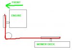
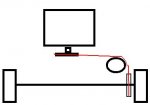
My thinking thus far has led me to the following theoretical set up: use a centrifugal clutch pulley on the engine running to a jackshaft, then another pulley system from jackshaft to rear axle; mount the jackshaft at a 45 degree angle in order to relieve the stress on the v-belts to make them last longer and decrease the amount of slippage compared to running a single v-belt from the engine clutch straight to the rear axle pulley with a 90 degree twist.

FIRST QUESTION: What do you guys/girls think about this set up? Should I keep it this way or just go ahead and spend the money on a horizontal shaft engine/clutch/chain and gears?

Also......I've heard that lawn mower engines have extremely light flywheels since the mower blade essentially acts as the engine's flywheel, and people who have used lawn mower engines have a hard time keeping them running because of this. Which brings me to my......

SECOND QUESTION: Would I need to somehow compensate for this if I use a lawn mower engine on a go kart or a minibike? If so, how would I do so?

This is all theoretical right now, but any input would be a great help to my possible summer project. Thanks!
 

Flexibel_kampfe

Hopeful for building kart
Messages
422
Reaction score
0
Location
RI
Couldnt you do what they did in some mills? A belt runs from the vertical member, turning 90o to the horizontal member. I mean, that was done with leather belts, but I imagine that a link belt could do the same, except better...

I mean those things were used to turn gigantic stones to crush grain(Windmill processor) all the way to 50" table saws....
 

bp011889

New member
Messages
11
Reaction score
0
Location
Texas
True, but those were with leather belts twisted over long distances (most about 3 feet). I'll be working with rubber v-belts that would be twisting over maybe a 6-10 inch distance (to fit the engine and jackshaft in a go kart / minibike); I think if I twisted one v-belt the full 90 degrees it would wear out too fast and have a lot of slippage, hence the thought of the jackshaft at 45 degrees with two belts.

Any other thoughts, ideas, comments?
 

robbie

New member
Messages
857
Reaction score
8
Location
Osceola, Missouri
When I was a kid we had a Montgomery Ward garden tractor with a 14 horse Briggs, built in the 1960s. The engine was oriented like a rear wheel drive car engine, and it had a car-type drive shaft coming out the back to the transaxle.

The mower deck was powered by a pulley on the front of the engine. The belt went down, then it turned 90 degrees to power the mower deck. The change of direction was done by two pulleys oriented in the same direction as the front tires, meaning that the belt came down off the front pulley and each leg of the belt wrapped around its own pulley at the front of the tractor, then went straight back to a pulley on a vertical shaft on top of the mower deck.

You could do a similar thing with a vertical shaft engine. Make the belt go toward the side of the kart and go around two pulleys, down to the wheel. The two pulleys would be mounted on a shaft that runs from front to back on the kart. If you build it right, you could mount the direction-changer-pulley axle on a hinged mount attached to a shift lever instead of spending the cash on a centrifugal belt drive clutch. Just push the lever into place to tighten the belt and go.

I don't know why I never thought of this before. It could be a pretty nice solution, and I happen to have a Briggs 8 hp mower engine sitting here at my place......
 

bp011889

New member
Messages
11
Reaction score
0
Location
Texas
to robbie:
I'm not quite getting the picture of how the belt and pulley system is oriented......any way you could draw up a pic and send it to me? email is bradleyalanbowler12@msn.com

ALSO: Third Question: I just realized that the mower engines, after further inspection, do NOT have an adjustable throttle (at least not an obvious one to me). Is there some way I could control the throttle via the governor, or do I need to look for a mower engine w/ an adjustable throttle to start with?
 

fowler

New member
Messages
5,463
Reaction score
17
Location
Bullsbrook West Aus
it will have an ajustable throttle it has to or it couldnt run
also the set up is talking about is (do this now)
get an elastic band and stretch it out with your hands to make a oval (like a belt)
then twist one hand back and the other foward so they are 90* apart
this is the shape it makes (the pullys go where your hands are
 

Attachments

  • stretching-rubber-band_~IS249-035.jpg
    stretching-rubber-band_~IS249-035.jpg
    15.7 KB · Views: 15

robbie

New member
Messages
857
Reaction score
8
Location
Osceola, Missouri
Here's how the setup would work. The first drawing is the old lawn tractor we used to have. The engine is in the front with a belt that goes around 2 pulleys, one on the right and one on the left. The 2 pulleys are free-wheeling and spin in opposite directions because the belt goes down on one and up on the other. This would be a long, 6 sided belt. The belt is shown in red.

The second drawing is a go kart, viewed from the rear. It's the same thing really, except backwards, and the belt goes off to one side. It would obviously take a much shorter belt. I would advise procuring the belt first and matching all your parts to it. Mount the two idler pulleys on a lever that pivots at the bottom, so the pulleys rotate down to the left to disengage the belt. If I remember correctly the old lawn tractor had an additional idler/tensioner pulley on the mower deck operated by a lever. You could do that easily enough.

Also, every lawnmower engine has a throttle. They're attached to the governor. All you have to do is remove the governor linkage and attach your accelerator pedal to the throttle lever on the carburetor.
 

Attachments

  • mowerbelt.jpg
    mowerbelt.jpg
    10.9 KB · Views: 14
  • kartbelt.jpg
    kartbelt.jpg
    9.9 KB · Views: 12

robbie

New member
Messages
857
Reaction score
8
Location
Osceola, Missouri
I think you could make it work, but you may have to put idlers in the right places to keep the belt lined up with the drive pulleys on each end.
 

bp011889

New member
Messages
11
Reaction score
0
Location
Texas
Hmmm that's definitely a different set up than anything else I've come across so far. What kind of belt is used for this? 'Cause I'm pretty sure a v-belt isn't going to twist around that far. I've thought about using o-ring belts for my jackshaft @ 45 degree angle set up, but I don't know where to buy them.....
 

robbie

New member
Messages
857
Reaction score
8
Location
Osceola, Missouri
Some mowers have 6 sided belts, which is sort of like two Vs on opposite sides. They're made this way to fit into the tensioner pulley on the outside of the belt. That's your best bet for a twisting setup, or for the 90 degree direction in my drawings.
 

bp011889

New member
Messages
11
Reaction score
0
Location
Texas
Sounds good, I might have to look into it. Only problem is after looking at all the parts to do stuff like this w/ the belts pulleys and jackshaft(s), its getting pricey. It'd almost be worth getting a horizontal engine and clutch......

I spotted an old tiller with a 5hp fun power briggs(?) horizontal shaft engine on it that i'm considering buying. Any advice as to what I should look at/inspect/test before I consider actually buying it?
 

TLOR FETT

New member
Messages
4
Reaction score
0
Any updates on if this system or any like it worked, I have a B&S vertical mower I want to be cheap with and make a ghetto cart.
 

redsox985

Active member
Messages
4,092
Reaction score
11
Location
PA
It may be costly but it would work. Get a right angle gear box with about a 1:1 or 1:1.2 ratio. Slip a piece of pipe over the drive shaft, weld the drive shaft to the input shaft of the RAGB with high heat for penetration, grind down the welds, slip the pipe over and weld on both sides just to reinforce. Then mount the motor and RAGB and put a cent. clutch on the output of the RAGB and chain to rear axle. It pretty much makes it a horizontal shaft motor with no high wear belts and slippage.
 

motor_head

expert garbage picker
Messages
479
Reaction score
1
Location
sutherland IA
if you mean weld on the output shaft of the motor, thats a terrible idea you can never take the motor apart if you do that
 

Kaptain Krunch

Pro Junk Collector
Messages
4,636
Reaction score
4
Location
vermont
would be better to simply get a coupler machined...welding to a crankshaft is a bad idea 99.9% of the time
 
Status
Not open for further replies.
Top