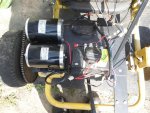
Upgrading a 48V 1,000W motor for more power

Status
Not open for further replies.

Functional Artist

Well-known member
Messages
5,650
Reaction score
3,285
Location
Toledo, Ohio
I did some more testing :thumbsup:

Still working with the ZY1020 48V 1,000W motor
...with just the contactor (for testing purposes) :cheers2:

This time I got some speed data too
...don't know why I didn't use the GPS on the earlier tests :huh:

So, for the ZY1020 motor (directly connected thru a solenoid/contactor)
...it seems like the data shows

Take off ~80A - 100A
Accelerating ~50A
Constant/crusin ~10A - 12A
Top Speed ~14 MPH
(& it gets up to 14 MPH pretty quick too) :2guns:

https://www.youtube.com/watch?v=jiVXFn8SzGA
 

Functional Artist

Well-known member
Messages
5,650
Reaction score
3,285
Location
Toledo, Ohio
More testing with the ZY1020 48V 1,000W motor
...this time with the Alfa Wheels YK31 48V 1,000W speed controller (the one that came with the motor)

For comparison purposes :thumbsup:

So, for the ZY1020 motor with the Alfa Wheels YK31 speed controller
...it seems like the data shows

Take off ~25A
Acceleration~25A
Constant/crusin ~12A
Top speed ~14 MPH
(it's top speed was 14 MPH too, it just took longer to get there)

https://www.youtube.com/watch?v=oyu1u5BluMc
 

Functional Artist

Well-known member
Messages
5,650
Reaction score
3,285
Location
Toledo, Ohio
Next test with the ZY1020 48V 1,000W motor that I wanna do
...is to try the TD Pro 48V 1,000W speed controller (it came with the MY1020 motor)

But, we've had a lot of rain lately
...so road testing, is on hold for a minute :censored:

Had some issues with the "data gathering" equipment during the last few tests (the meter floppin' around & battery issues)

So, I was thinkin' :idea2:
...why not re-do the dash
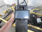
...better yet, let's build a "data" center :thumbsup:


e-Lemon-aid already has a couple of switches mounted to a small plastic "dash board" below the steering wheel

But, that's kinda low to easily see & record data :ack2:

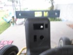
Above (& kinda next to) the steering wheel seems like the best spot

Don't want just an open dash situation (with the back side of the instruments & all of the wiring hangin' out & exposed)

So, an enclosed dash (or forward control box, as Sid would call it)
...is probably the best way to go :cheers2:

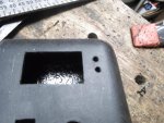
Speaking of "forward control box", maybe I can use the box I made/set up for El Dingo way back when

It's way too big, so we'll have to cut it down a bit
...but, if I turn it sideways

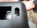
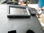
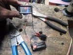
I can mount the amp/volt meter, in the existing hole (just upside down from the way it was before)
...put a DPST (dual pole) switch, next to the meter
(that can be used to turn both the meter & a speed controller on (or) off)
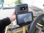
…& also use the ledge/lip to help support the GPS :2guns:
 

Attachments

  • SAM_1799.jpg
    SAM_1799.jpg
    651.4 KB · Views: 1
  • SAM_1803.jpg
    SAM_1803.jpg
    596.7 KB · Views: 0
  • SAM_0108.jpg
    SAM_0108.jpg
    245.7 KB · Views: 0
  • SAM_0109.jpg
    SAM_0109.jpg
    250.3 KB · Views: 0
  • SAM_0111.jpg
    SAM_0111.jpg
    222.9 KB · Views: 0
  • SAM_0114.jpg
    SAM_0114.jpg
    202.1 KB · Views: 0

Functional Artist

Well-known member
Messages
5,650
Reaction score
3,285
Location
Toledo, Ohio
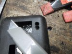
First, I marked, drilled & then cut/shaped the hole for the switch

Using the WPI (work piece indicator) method
...work it a little, check it, work it a little more, check it again
...til' it fits nicely :thumbsup:

Then, cut the box off, with a hack saw, just below the shelf/lip for the GPS

Took it back to the kart
...checked for placement
...& came up with a "good-n-strong" bracket for mounting :2guns:
 

Attachments

  • SAM_0144.jpg
    SAM_0144.jpg
    230.7 KB · Views: 0
  • SAM_0143.jpg
    SAM_0143.jpg
    257.7 KB · Views: 0
  • SAM_0142.jpg
    SAM_0142.jpg
    226.9 KB · Views: 0
  • SAM_0140.jpg
    SAM_0140.jpg
    315 KB · Views: 0
  • SAM_0137.jpg
    SAM_0137.jpg
    269.6 KB · Views: 0
  • SAM_0151.jpg
    SAM_0151.jpg
    217.5 KB · Views: 0
  • SAM_0150.jpg
    SAM_0150.jpg
    219.3 KB · Views: 0
  • SAM_0149.jpg
    SAM_0149.jpg
    281.5 KB · Views: 0
  • SAM_0148.jpg
    SAM_0148.jpg
    324.2 KB · Views: 0
  • SAM_0147.jpg
    SAM_0147.jpg
    231.3 KB · Views: 0

Functional Artist

Well-known member
Messages
5,650
Reaction score
3,285
Location
Toledo, Ohio
Checked to be sure the data center would sit level
...marked & drilled the mounting holes
…then, painted the mounting bracket

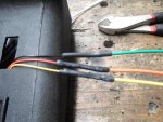
While it was drying, I worked on the wiring

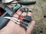
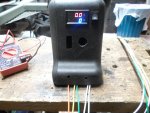
I used a DPST switch to control both the power to the meter & the speed controller (when used)

* I want to just use a "simple" voltage divider to power the meter right from the 48V battery pack

Still workin' on that so, for now, I am just using a 9V battery mounted inside the data center box

I also attached some extension wires to the signal leads

Yup, that should work :thumbsup:
 

Attachments

  • SAM_0172.jpg
    SAM_0172.jpg
    322.7 KB · Views: 0
  • SAM_0168.jpg
    SAM_0168.jpg
    297.3 KB · Views: 0
  • SAM_0163.jpg
    SAM_0163.jpg
    341.7 KB · Views: 0
  • SAM_0152.jpg
    SAM_0152.jpg
    170.6 KB · Views: 0
  • SAM_0151.jpg
    SAM_0151.jpg
    217.5 KB · Views: 0
  • SAM_0174.jpg
    SAM_0174.jpg
    279.1 KB · Views: 0

TT540

Newb
Messages
347
Reaction score
7
Location
Huntsville, AL
If the meter takes in 12 volts you can just pick off one of the 12 volt battery positive leads and Supply that to the meter. That means you would use the battery that shares the ground for the system. so the first battery in the system makes 12 volts, the second battery makes 24 volts and so on Down the Line.
 

Functional Artist

Well-known member
Messages
5,650
Reaction score
3,285
Location
Toledo, Ohio
If the meter takes in 12 volts you can just pick off one of the 12 volt battery positive leads and Supply that to the meter. That means you would use the battery that shares the ground for the system. so the first battery in the system makes 12 volts, the second battery makes 24 volts and so on Down the Line.

Yup, you are correct
...but, that concept can/will cause your battery pack to become "unbalanced" (bad for lead acid, way worse for lithium) :ack2:

I am glad you brought it up though :thumbsup:

You probably already know, but, I'll explain anyways (for the class) :cheers2:

From what I understand & also proven (to/for myself) thru personal testing
...is that it's not/never a good idea to draw power from a "cell" or part of your battery pack

Because while your draining the whole pack to power your motor
…the (1) battery powering the meter would be working harder (doing double duty)
...& @ the end of your ride, the battery pack should/would be "out of balance"

So, to "properly" re-charge the entire pack
...that (1) battery (cell) would first need "individual" attention
(it would need to be charged back up "even" with the rest of the pack/cells)
...then the entire pack could be "safely" charged :2guns:

If just re-charged in this "condition" either
...(best case scenario) the (1) cell would never get charged to full capacity
(the charger would shut off when the other cells showed "full")
or
(worst case scenario) the charger would "over charge" the other cells trying to bring the (1) cell up to "full")

* A battery pack should be thought of & treated as (1) unit
...it should always be discharged & re-charged as evenly as possible

Even when building a battery pack (connecting individual batteries/cells together)
..."ideally" everything should have very closely matching resistances (every cell, the connectors & even the connections)
 

Functional Artist

Well-known member
Messages
5,650
Reaction score
3,285
Location
Toledo, Ohio
I got the "data center" done & installed :2guns:
...& it stopped raining

So, I did one more test with the ZY1020 48V 1,000W motor
...this time with a TD Pro YK31C 48V 1,000W speed controller

I did several test runs :thumbsup:
...but, the battery in my camera "died" like, 2 minutes into the test :ack2:

The data wasn't much different from the earlier tests using the Alfa Wheels speed controller

Take Off ~30A
Acceleration ~30A
Constant/crusin ~10A

The amp draw seems a bit higher (TD Pro-30A vs. Alfa Wheels-25A)
...but, the top Speed was still ~14 MPH :cheers2:

https://www.youtube.com/watch?v=wRxr30viYNg
 

Functional Artist

Well-known member
Messages
5,650
Reaction score
3,285
Location
Toledo, Ohio
Personal Analysis, of the (3) tests with the ZY1020 48V 1,000W motor

Alfa Wheels speed controller

Take-off ~25A
Accelerating ~25A
Constant/crusin' ~12A
Top speed ~14 MPH

TD Pro speed controller
Take-off ~30A
Accelerating ~30A
Constant/crisin ~10A
Top speed ~14 MPH

With-out a speed controller (just a battery pack, beefy switch & motor)

Take-off (up to) ~100A
Accelerating ~50A
Constant/crusin ~10A - 12A
Top speed ~14 MPH

So, (as Sid said) the speed controller (available amps) doesn't seem to be holding the motor back :cheers2:

The only advantage, I see, is a "harder" acceleration :auto:
...but, at the expense of "lots" of amps :ack2:
…& the top speed was still ~14MPH either way :2guns:
 

Functional Artist

Well-known member
Messages
5,650
Reaction score
3,285
Location
Toledo, Ohio
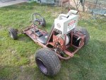
So, we can compare the data between a ZY 1020 motor & a MY 1020 motor, I mounted a MY1020 48V 1,000W motor on e-Lemon-aid & did some more testin' (this is fun!) :cheers2:

For the first test, I connected the Alfa Wheels speed controller
...here are the results :2guns:

Take off ~25A
Constant/crusin' ~9A

Top speed 14 MPH

The video is "super" short but, ya get the point :thumbsup:

https://www.youtube.com/watch?v=uG3dvgL_C8M
 

Attachments

  • SAM_0330.jpg
    SAM_0330.jpg
    409.7 KB · Views: 3

Functional Artist

Well-known member
Messages
5,650
Reaction score
3,285
Location
Toledo, Ohio
The final tests with the MY1020 48V 1,000W motor
...are the "Hold on to your Hat" tests :thumbsup:

It's just a battery pack, motor & a contactor or "beefy switch"
...so, "hit the button" & "Hold on to your Hat" :auto:

First, I did an "against the wall" test
...the max amp draw (I recorded) was ~85A

Then, I did some road testin' :2guns:
Take off ~80A - 100A
Constant/crusin ~10A

Top speed was (also) 14 MPH :cheers2:

The motor got "warm" during "normal" testing
...but, I noticed that the motor was "really" hot, after these "High Amp" tests :ack2:

https://www.youtube.com/watch?v=OAJCPw6KS7g
 

TT540

Newb
Messages
347
Reaction score
7
Location
Huntsville, AL
Outstanding! I love how she did not need to be told to take a few steps back before you hit it. A wheelie bar would be a nice addition. Angle it just right and you might can sustain the wheely for a long time.
 

Functional Artist

Well-known member
Messages
5,650
Reaction score
3,285
Location
Toledo, Ohio
Outstanding! I love how she did not need to be told to take a few steps back before you hit it. A wheelie bar would be a nice addition. Angle it just right and you might can sustain the wheely for a long time.

I think the first "lift" scared me just as much as her :smiley_omg:

Yup, she knows "what's up"
...she's my "little Danika" :thumbsup:

...but, after these tests, she told me

"I don't wanna test that one, Dad" :lolgoku:
...give her a few years :auto:
 

Functional Artist

Well-known member
Messages
5,650
Reaction score
3,285
Location
Toledo, Ohio
Hey Sid,

Could you give us some some expert analysis on these tests? :cheers2:

...My1020 vs. ZY1020?

...Alfa Wheels speed controller vs. TD Pro speed controller?

...speed controller vs. "beefy switch"?


I am thinking about ordering some different sized driven sprockets for the next set of tests
...like a 50T (5:1), 45T (4.5:1) & 35T (3.5:1) :2guns:

Any suggestions? :idea2:
 

TT540

Newb
Messages
347
Reaction score
7
Location
Huntsville, AL
A Speed controller creates "pulses" of voltage to the motor. This voltage is the same as the battery voltage. Essentially, it is a lot like the beefy switch when you tried to pulse it to keep from flipping over. Only, the controller does this very fast. The ratio of the controller's pulse going high (beefy switch closed) to pulse low (beefy switch open) is equal to "throttle percentage". Also known as duty cycle. If the pulse is 90% "on" and 10% off, then your gas pedal is at 90% pressed.

There is a lot more science to Pulse Width Modular and frequency and blah blah, but essentially the controller is a grouping of beefy "silicon IC switch".

When you pushed the beefy switch, that is the same as a 100% duty cycle, 100% throttle, full and constant voltage to the motor. A motor that is just a bunch of wound wire with very little resistance and some magnets. So the current goes sky high.

In a prior post I made a recommendation to have a beefy switch as well as the controller to get the most wide open throttle efficiency for full speed operations. This will keep heat out of the controller, but also add complexity to your setup. Any time heat is created, power is lost. I think you could simply do a beefy switch in parallel, but then you'd have to consider the hold up current needed to keep that solenoid closed for long period. They have SERIOUS springs inside of them to prevent the contacts from arcing closed. If that cover was off of your beefy switch, you would see a significant blue spark at the contacts when you closed and opened that switch/circuit.

What you have built with the beefy switch concept is a very aggressive Power Wheels. those have no progressive throttle control.. Just a switch and hold on to the steering wheel.
 

Functional Artist

Well-known member
Messages
5,650
Reaction score
3,285
Location
Toledo, Ohio
A Speed controller creates "pulses" of voltage to the motor. This voltage is the same as the battery voltage. Essentially, it is a lot like the beefy switch when you tried to pulse it to keep from flipping over. Only, the controller does this very fast. The ratio of the controller's pulse going high (beefy switch closed) to pulse low (beefy switch open) is equal to "throttle percentage". Also known as duty cycle. If the pulse is 90% "on" and 10% off, then your gas pedal is at 90% pressed.

There is a lot more science to Pulse Width Modular and frequency and blah blah, but essentially the controller is a grouping of beefy "silicon IC switch".

When you pushed the beefy switch, that is the same as a 100% duty cycle, 100% throttle, full and constant voltage to the motor. A motor that is just a bunch of wound wire with very little resistance and some magnets. So the current goes sky high.

In a prior post I made a recommendation to have a beefy switch as well as the controller to get the most wide open throttle efficiency for full speed operations. This will keep heat out of the controller, but also add complexity to your setup. Any time heat is created, power is lost. I think you could simply do a beefy switch in parallel, but then you'd have to consider the hold up current needed to keep that solenoid closed for long period. They have SERIOUS springs inside of them to prevent the contacts from arcing closed. If that cover was off of your beefy switch, you would see a significant blue spark at the contacts when you closed and opened that switch/circuit.

What you have built with the beefy switch concept is a very aggressive Power Wheels. those have no progressive throttle control.. Just a switch and hold on to the steering wheel.

Well put :thumbsup:

Yup, these were just tests
...this is NOT the "proper or safe way" to control the speed of an electric motor :ack2:

But, it looks like these tests proved that (like Sid said :thumbsup:)
..."adding more amps"
...or using a speed controller with a higher "available amperage output"
...WILL NOT increase the "power" or speed of an electric motor (at least these little PM motors)

They definitely "take off" harder :smiley_omg:

but, the continuous/cruzin' amp draw & the overall top speed
...was about the same (with or without the speed controller) :2guns:
 

snowball

New member
Messages
11
Reaction score
0
Just wanted to share my experience pulling extra power out of a 48V, I ran a similar setup with a 200A 48V kelly controller + two MY1020s in parallel off the single controller for a combined 2000W

Power:
We used a very comprehensive multimeter screen for testing
peak: 5000W for one second
load: 1800W constant
continuous: 500W cruising

Current draw:
Peaked at around 80A during load, hovered around 25A when cruising.

Gearing was set for top speed @ 25mph (4" wheels, 11" tires) and it had no trouble getting up hills, vehicle weighed 180 lbs without driver. We tested current draw off both motors and they were within 5%. Battery lasted a good 25-30 min before dropping below 48V.
 
Status
Not open for further replies.
Top