Two Stroke Mini Bike

Status
Not open for further replies.

Desertduler

Active member
Messages
1,736
Reaction score
14
one thing I know..
that thing should not see paint (clear coat yes.. color.. NOPE!).

Another thing I wonder..
have you thought about tilting the engine forward a bit?
I mean that'd look mean, wouldn't it?
Well maybe not till it's flush with the lower tubes, but maybe -what?- half way??

'sid
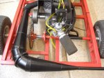
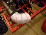
I plan on tilting the engine forward. I have decided to put the exhaust port forward and build a old school down pipe expansion chamber that will run under the frame, Hmmm, I never thought about clear coating the plain steel, we will see, good suggestion, I guess that I should have posted this thread in the project log, my bad, maybe this thread will have to be moved there?

---------- Post added at 09:26 PM ---------- Previous post was at 09:25 PM ----------

That is the most awesome thing ive seen in awhile.
Thanks Karl, just having fun!
 

Desertduler

Active member
Messages
1,736
Reaction score
14
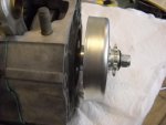
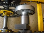
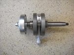
I have machined the crankshaft down and milled a 1/4 inch keyway slot in the crankshaft to accept the clutch, soon I will build the lower end of the engine.
 

Attachments

  • 003.jpg
    003.jpg
    322.6 KB · Views: 9

Desertduler

Active member
Messages
1,736
Reaction score
14
Man that looks nice!
Thanks Paul, the crankshaft in this engine is made out of some really tough steel, I could only mill about .002 at a time milling the slot using a .250 Cobalt end mill at a final depth of .125, plus I could not drill the end of the crankshaft to tap it to 7/16 NF so I used the existing 1/2 NF threads that were left in the crankshaft after I had trimmed the end of it down in my lathe and I threaded a grade 8 Dorman 1/2 NF bolt in the end of the crank and I used Loctite 271 to retain the bolt in the crankshaft then I cut the overall length of the bolt to my needs and then I set the whole assembly up in my lathe and I turned down the 1/2 bolt down to 7/16 and I threaded the end of the turned down bolt to 7/16 NF so that I can retain the clutch to the crankshaft. What we will do just to have a little fun!
 

Desertduler

Active member
Messages
1,736
Reaction score
14
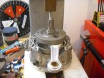
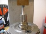
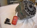
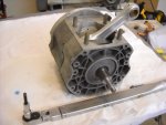
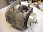
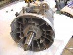
Here are some photos of the lower end of the engine while I assembled it. I used my arbor press to press in the crankshaft seals, magneto side bearing, and the crankshaft into the magneto side of the crankcase. Here one can see the machine work that I described in my previous post that I had to do in order to adapt this clutch to this old two stroke.
 

Attachments

  • 001.jpg
    001.jpg
    292.3 KB · Views: 11
  • 003.jpg
    003.jpg
    227.1 KB · Views: 12
  • 007.jpg
    007.jpg
    259.1 KB · Views: 16
  • 008.jpg
    008.jpg
    240.4 KB · Views: 9
  • 011.jpg
    011.jpg
    225.6 KB · Views: 10
  • 015.jpg
    015.jpg
    225.9 KB · Views: 8
  • 013.jpg
    013.jpg
    260.1 KB · Views: 9

chancer

ɔ ɥ ɐ u ɔ ǝ ɹ
Messages
9,358
Reaction score
93
Location
COMFORT, TEXAS
Dude that is so cool. The way you made that bolt work! But you said you used 271 loctite and the pic shows 243. :toetap05:
Just kidding.
 

Desertduler

Active member
Messages
1,736
Reaction score
14
Dude that is so cool. The way you made that bolt work! But you said you used 271 loctite and the pic shows 243. :toetap05:
Just kidding.
Lol, the 243 was used on the socket headed crankcase screws, I use 271 for things that you don't want to fly off at high RPM's.
 

Desertduler

Active member
Messages
1,736
Reaction score
14
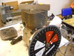
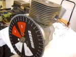
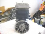
Here I am using a solid H bar puller section as a slug stop in order to find absolute T.D.C.
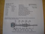
After that task is completed I measure the exhaust and transfer port duration they are as follows for this engine, 186 degrees for the exhaust and 126 degrees for the transfer ports. Then the exhaust port opening diameter and shape must be measured at the cylinder exhaust port gasket surface then the exhaust gasket that is going to be use is put into place and with the piston covering the exhaust port I measure the distance from the piston in the center of the port to the installed center of the gasket outer surface in order to get that dimension and it is 44 mm. I enter my figures in my computer expansion software program and I start playing around with Brake Mean Effective Pressure or B.M.E.P figures until I obtain my desired power level and power band width and here is the pipe design that I have selected for this engine that I will build for this mini bike. Just as a note section "E" can be added to section "C'' of the pipe in order to shorten the tuned pipe overall length which I plan on doing. This tuned pipe is a mild state of tune for this engine with a B.M.E.P. of 8.33 which in turn will give this engine a wider power band.
 

Attachments

  • 001.jpg
    001.jpg
    320 KB · Views: 7
  • 004.jpg
    004.jpg
    279.1 KB · Views: 7
  • 006.jpg
    006.jpg
    250.2 KB · Views: 13

Desertduler

Active member
Messages
1,736
Reaction score
14
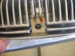
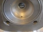
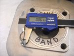
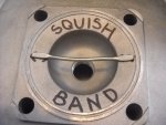
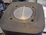
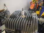
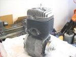
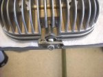
I checked the squish band on this engine and at .0615 I am going to leave it as it is because the engine has an forged aluminum connecting rod and a forged piston which will expand and lengthen
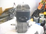
at a greater rate than the cast iron cylinder will plus the connecting rod will stretch to a degree thus reducing the squish band clearance while the engine is up to temperature and running. I drilled and tapped the cylinder head to accept the compression release. In the pictures there is a sharpie mark on the insulator this is the location of the spark plug ground wire which on a two stroke should face the exhaust port thus indexing the spark plug correctly in the combustion chamber. I painted the cast iron cylinder with VHT high temp paint, this engine is ready for the next assembly phase.
 

Attachments

  • 017.jpg
    017.jpg
    286.9 KB · Views: 5
  • 014.jpg
    014.jpg
    291.4 KB · Views: 5
  • 013.jpg
    013.jpg
    294.5 KB · Views: 6
  • 010.jpg
    010.jpg
    364.6 KB · Views: 6
  • 007.jpg
    007.jpg
    267.2 KB · Views: 5
  • 029.jpg
    029.jpg
    220 KB · Views: 6
  • 025.jpg
    025.jpg
    216.8 KB · Views: 5
  • 024.jpg
    024.jpg
    290.8 KB · Views: 6
  • 022.jpg
    022.jpg
    208.4 KB · Views: 6
  • 018.jpg
    018.jpg
    290.1 KB · Views: 4

chancer

ɔ ɥ ɐ u ɔ ǝ ɹ
Messages
9,358
Reaction score
93
Location
COMFORT, TEXAS
Well.... This is just (I know as if) a motor. and the build off starts soon. So I have a feeling we will be seeing more.
 

Desertduler

Active member
Messages
1,736
Reaction score
14
Well.... This is just (I know as if) a motor. and the build off starts soon. So I have a feeling we will be seeing more.
Well you will be seeing more, I do not plan on entering this mini bike in this years build off, once is enough for me I don't like doing things twice sometimes no matter what the out come is, I would like to see some of the other members here on this site build something in this years upcoming build off and you are going to do it so my hats off to you for doing so. :thumbsup:
 

Denny

Canned Monster
Messages
11,923
Reaction score
8,418
Location
Mayberry, Indiana
Brett, are you going to hydroform you're pipe or are you going to do it the old fashioned way by welding all the pieces together?

Denny
 

Desertduler

Active member
Messages
1,736
Reaction score
14
Brett, are you going to hydroform you're pipe or are you going to do it the old fashioned way by welding all the pieces together?

Denny
Denny, I will make the pipe just like I did on my red kart with the Rotax 277. First I make a paper pipe and then transfer the pattern sections to sheet metal cut the sheet metal sections out and roll them up in my slip roller and weld all the sections together. Here is the one that I built for my flying red pig along with a picture of the paper belly section 90 degree mock up as I was building the pipe for the Rotax 277.
 

Attachments

  • 002.jpg
    002.jpg
    363.3 KB · Views: 11
  • 019.jpg
    019.jpg
    303.4 KB · Views: 10

Denny

Canned Monster
Messages
11,923
Reaction score
8,418
Location
Mayberry, Indiana
It just seems like a lot of work to me. But, I bow to you're skills and patience. I did not realize how quick and easy it was to hydroform a pipe until one of my golf cart customers wanted me to build him a pipe for his bike and brought me his design. That's why I asked.

Denny
 

NewbCarter

Member
Messages
403
Reaction score
4
Location
Solin , Croatia
Iv seen people make pulse jets with pressure washers . Weld the general shape of it , drill a hole for a pressure washer to hook up to , and let it blast . After its done you trim the edges and make repairs if needed .

Nice work as always Brett , waiting to see the first startup . Also , this one way bearing / clutch could be used on direct drive gokart engines ? As long as the engine isnt too powerful for the clutch ?

EDIT : if i may ask , what is that clutch rated for ?
 

Desertduler

Active member
Messages
1,736
Reaction score
14
It just seems like a lot of work to me. But, I bow to you're skills and patience. I did not realize how quick and easy it was to hydroform a pipe until one of my golf cart customers wanted me to build him a pipe for his bike and brought me his design. That's why I asked.

Denny
I have indeed seen videos of people hydro forming expansion chambers and that would be a quick way but I am in no hurry as I have all the time in the world pretty much now being as I am retired!:lolgoku:
No seriously I enjoy building expansion chambers the way that I have described it does take a lot of work and it really makes you use your brain with all the shape figures and fitment of the sections plus as you go along making a mock up paper pipe you can alter the sections angles to tweak the pipe configuration if need be then when it is right I print out another complete paper pattern of each of the sections then I number them in order starting with the first section that starts at the exhaust port as number 1 and continue on until I have a complete record of all the sections and I store them just in case if a section of the pipe gets damaged in a crash or for other mishaps which can happen then I could replace that section or sections because I have saved all the pattern sections of the pipe and that way I would not have to build another complete pipe.
 

Desertduler

Active member
Messages
1,736
Reaction score
14
Iv seen people make pulse jets with pressure washers . Weld the general shape of it , drill a hole for a pressure washer to hook up to , and let it blast . After its done you trim the edges and make repairs if needed .

Nice work as always Brett , waiting to see the first startup . Also , this one way bearing / clutch could be used on direct drive gokart engines ? As long as the engine isnt too powerful for the clutch ?

EDIT : if i may ask , what is that clutch rated for ?
Thank you, when you ask about direct drive go kart engines what comes to my mind is a engine with just a sprocket on the output shaft and of course if you had a one way bearing inside just a drive sprocket you could bump start the kart and when the engine started the kart would never move but I think that you are just asking about the use of a one way bearing as I am using in a go kart application? If the clutch uses a needle bearing as an idler bearing then one could replace the bearing as I have with a one way bearing and be able to bump start the kart but if the engine being used has a way being started recoil, electric, etc this modification would be senseless unless one would want engine braking all the way down until the engine pto rpm over ran the clutch drum rpm. This bearing has nothing to do with the rating of the clutch capabilities, shoe contact surface and shoe contact force and shoe material have a factor on how much HP an centrifugal clutch will handle in the case of this clutch I have used this same clutch now on my Rotary Engine powered karts since I built them and they have been bullet proof but that was after I have modified them for my use, they hook up with out slipping both on and off asphalt. My Wife's Kart engine puts out some real good power and I have used the kart hard without having any clutch problems. Here is a photo of the modified clutch that I have used on this Rotary engine after it has been on my kart and used hard and now it is on her kart, notice that the clutch drum does not show any signs of heat discoloration due to slippage, that is because I have modified the clutch shoes to be able to pin down the power out put of these high hp engines which are at least 25 to 30 hp. This clutch in it's stock form could not handle the out put of any of these engines that I am using them on so their original rating goes out the window.
 

Attachments

  • 008.jpg
    008.jpg
    296.6 KB · Views: 6
Status
Not open for further replies.
Top