Tire alignment issues with shock compression - Trick to A-Arm/Tie rod placement?

Econdron

Member
Messages
47
Reaction score
40
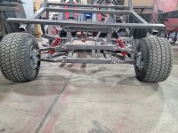
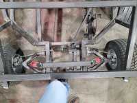
I attached a picture of my karts front end. It took me a long time to figure out what was happening here, but I think I finally got it figured out. When you stand on the front end of the kart and compress the springs, the A-Arms rotate upwards, and thus move outwards slightly, enough to start pulling on the tie rods, causing the wheels to no longer be aligned. When you release pressure, they go back to being aligned. I've spent some time studying this, but this is such a common setup on go karts, ATV's, even cars, I must be missing something. It's pulling hard enough on the tie rods that it stops compressing the springs, because it's trying to stretch the tie rods, if that makes sense.

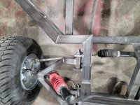
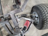
Is there a geometry trick to placing the rack and pinion and/or the A-arm angles? I've seen those rock crawlers that have wheels move several inches independently from each other without messing with the alignment of the wheels. I even saw a Grand daddy build, similar to mine, do the same thing.

My current plan is to just adjust the shock spacing so the resting place of the A-arms is closer to horizontal, as opposed to the downward pitch it currently has, so I'll have less outward movement as the wheels come up and down, but I'm still limited to only 2-3 inches of vertical travel.
 

Attachments

  • 20230426_154311.jpg
    20230426_154311.jpg
    2.2 MB · Views: 14

Bansil

Painter of gnomes....
Messages
1,414
Reaction score
1,113
Location
Mnts of the farthest NE TN you can go
Biggest thing is the upper/lower A-arms have to have the same spacing and length also steering knuckles have same distance between mounts

So as suspension moves up and down the wheel mount surface stays the same, parallel to frame or whatever camber you built in

Same thing with the steering, mounts have to travel with suspension and not change lengths, if they change lengths, they change the toe angle

Does that make sense?

Thats one reason IRS bugs are better than swing arm bugs, when you lift the swing arm bugs the camber changes extreme on the back.

IRS bugs remain perpendicular to frame work, when building a rail

noitce how everything stays the same? Same principal

1-4link.jpg
 
Last edited:

Hellion

Moderator
Messages
8,642
Reaction score
3,716
More photos please.

Bansil is onto something, it looks like the upper and lower arms have different mounts relative to each other.
 

Econdron

Member
Messages
47
Reaction score
40
Biggest thing is the upper/lower A-arms have to have the same spacing and length also steering knuckles have same distance between mounts

So as suspension moves up and down the wheel mount surface stays the same, parallel to frame or whatever camber you built in

Same thing with the steering, mounts have to travel with suspension and not change lengths, if they change lengths, they change the toe angle

Does that make sense?

Thats one reason IRS bugs are better than swing arm bugs, when you lift the swing arm bugs the camber changes extreme on the back.

IRS bugs remain perpendicular to frame work, when building a rail

noitce how everything stays the same? Same principal

View attachment 138538
It sounds like you know exactly what my problem is, but I'll be honest, you lost me a little bit. I attached some more pictures. The one shows my foot pushing down the front end, you can see the tire on the right is turned outwards a little and the tire on the left is still straight.

If I had to guess, after reading your post and looking at the build a little more, it seems maybe the issue is that the tie rods are not running parallel to the A-Arms? So they are rotating on a different radius than the A-Arms?
 

Attachments

  • 20230530_082235.jpg
    20230530_082235.jpg
    3.9 MB · Views: 7
  • 20230530_082242.jpg
    20230530_082242.jpg
    3.6 MB · Views: 7
  • 20230530_082246.jpg
    20230530_082246.jpg
    3.7 MB · Views: 5
  • 20230530_082251.jpg
    20230530_082251.jpg
    4.4 MB · Views: 6
  • 20230530_082307.jpg
    20230530_082307.jpg
    4.4 MB · Views: 7

Snaker

Active member
Messages
341
Reaction score
183
Biggest thing is the upper/lower A-arms have to have the same spacing and length also steering knuckles have same distance between mounts

So as suspension moves up and down the wheel mount surface stays the same, parallel to frame or whatever camber you built in

Same thing with the steering, mounts have to travel with suspension and not change lengths, if they change lengths, they change the toe angle

Does that make sense?

Thats one reason IRS bugs are better than swing arm bugs, when you lift the swing arm bugs the camber changes extreme on the back.

IRS bugs remain perpendicular to frame work, when building a rail

noitce how everything stays the same? Same principal

View attachment 138538

I think your mixing up camber with steering.
Suspensions are often set up with what I know as "unequal radius arms".
That can be very noticable when you see a long suspension machine land and the bottoms of the wheels squish way out from vertical.
There are benefits to that.
But doing that doesn't affect the steering.
 

Snaker

Active member
Messages
341
Reaction score
183
It sounds like you know exactly what my problem is, but I'll be honest, you lost me a little bit. I attached some more pictures. The one shows my foot pushing down the front end, you can see the tire on the right is turned outwards a little and the tire on the left is still straight.

If I had to guess, after reading your post and looking at the build a little more, it seems maybe the issue is that the tie rods are not running parallel to the A-Arms? So they are rotating on a different radius than the A-Arms?

Bump steer is when the tie rods don't end at or close to the suspension pivots.
The triangulation changes throughout the travel and turns the wheel.
What I see from the pictures is that your steer rack is set left of center.
The left tie rod appears to end at about the suspension pivot, but the right tie rod is much longer and ends quite a ways inboard of the suspension pivot.
If your setup had no front suspension it would be fine, but alas, you have suspension.

Two ways I can think of to solve:
1. Setup a inline pivot rod so as to make the right tie rod end at the suspension pivot, and possibly the left side as well if necessary.
2. Get a steering setup from one of the China side by side carts.
They typically use ujoints in the steering wheel shaft to get the rack centered.
Then adjust your stance to fit that setup.
 

Econdron

Member
Messages
47
Reaction score
40
Bump steer is when the tie rods don't end at or close to the suspension pivots.
The triangulation changes throughout the travel and turns the wheel.
What I see from the pictures is that your steer rack is set left of center.
The left tie rod appears to end at about the suspension pivot, but the right tie rod is much longer and ends quite a ways inboard of the suspension pivot.
If your setup had no front suspension it would be fine, but alas, you have suspension.

Two ways I can think of to solve:
1. Setup a inline pivot rod so as to make the right tie rod end at the suspension pivot, and possibly the left side as well if necessary.
2. Get a steering setup from one of the China side by side carts.
They typically use ujoints in the steering wheel shaft to get the rack centered.
Then adjust your stance to fit that setup.
That's what I was thinking, but when you turn, doesn't that just un-align everything as the pivot points move with the tie rods? Or maybe that's not such a big deal if you get some bump steer while you're already turning?
 

Snaker

Active member
Messages
341
Reaction score
183
That's what I was thinking, but when you turn, doesn't that just un-align everything as the pivot points move with the tie rods? Or maybe that's not such a big deal if you get some bump steer while you're already turning?

Not really because the tie rod length still stays the same.
But the closer the better.
When this kind of stuff had very short suspension travel. things were close enough to work ok.
As travel increases, the little issues become big issues.
You have a good sample right there comparing the right side to the left side
Mfgrs spend big time and money on little things like that to tweak a bit and compare.
 

Bansil

Painter of gnomes....
Messages
1,414
Reaction score
1,113
Location
Mnts of the farthest NE TN you can go
I think your mixing up camber with steering.
Suspensions are often set up with what I know as "unequal radius arms".
That can be very noticable when you see a long suspension machine land and the bottoms of the wheels squish way out from vertical.
There are benefits to that.
But doing that doesn't affect the steering.
No, I was being really general in how different mounting points,lengths of arms/links etc effect different setup.
An example:
2nd generation rodeos have a 4link and panhard bar, the point the 4links converge is actually like 8 ft back and 18 inches below grade. So on slow, hightraction the climbs the rear-end actually unloaded due to wt transfer.
So I raised the top links like 6 inches, this moved the wt transfer more towards top bell housing bolt and resulted in a way improved climb.

Disclaimer: those numbers are made up, you can google Planetisuzoo and the turtle or team turtle.

I USED this example because I learned how all points worked, and for high traction climbs in TN,KY and NC, I was able to change the suspension rather easy....10 folks are running that setup or were, long time ago
 
Top