Tarantula in Albuquerque

Status
Not open for further replies.

SDCoston

New member
Messages
51
Reaction score
0
Location
Albuquerque, NM
Hi,

[this is a variant of a post I made in the introductions section of this forum a couple of weeks ago - I figured I'd migrate to the projects section]

The first week of July 2012, my 12 year old son reminded me that 2 years ago I had promised to build a go-kart with him when he was 12. I vaguely remember the promise and my hopes that it would be a passing idea, given my lack of experience in such things.

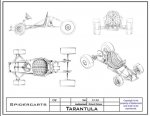
Nevertheless, I immediately started doing a bunch of research and, for good or bad, landed on the SpiderKarts website and downloaded a bunch of plans. I then went out and bought a TIG welder / plasma cutter and spent a bunch of time researching "all things welding" on the internet. I decided to build a "Tarantula" model, and started acquiring stuff ... metal, parts, etc.

I found that it took me about scary 30 minutes to figure out how to adjust and use my TIG welder to make welds that don't look great, but that I can't break with a sledge hammer.

The kart plans are fairly complete, though I've found some things that didn't work well for me and I had to make small modifications.

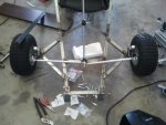
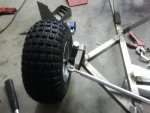
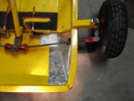
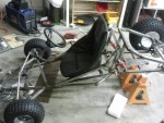
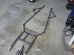
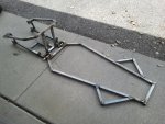
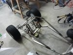
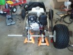
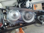
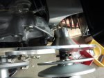
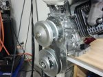
I'll start by posting pictures of my build as it progressed to "document" my experiences for anyone who tries to build the Tarantula in the future, in the hopes that they may be helpful.

Sean
 

SDCoston

New member
Messages
51
Reaction score
0
Location
Albuquerque, NM
I started out exactly as the plans instruct.

Here is the lower half or base of the "sub frame" which holds the engine and the bearing hangers for the live axle, and the base of the front part of the kart.

As I cut pieces with my cheapo Harbor Freight chop saw, I realized that spending an extra $100 on something with a cast aluminum base that wouldn't flex when the vise is clamped down would have been a good idea.

I just used the floor of my garage to assure that the frame pieces were on the same plane.
 

Attachments

  • 2012-07-18 06.41.16.jpg
    2012-07-18 06.41.16.jpg
    69.4 KB · Views: 41

SDCoston

New member
Messages
51
Reaction score
0
Location
Albuquerque, NM
The spiderkart plans for the Tarantula called for a 6.5HP (or thereabout) engine. After consulting with a friend who advised "bigger is always better," I decided to buy a Honda 390 13HP engine because I want to ride it as well as my kiddos.

The upper part of the plan's "subframe" was designed for the smaller engine, so I modified it simply by welding in additional widths of 1"square tubing outside of the upper attachment to the bearing hanger.

I thus finished the subframe and used the plan's recommended process for welding on the spindle brackets and attaching the subframe to the base of the main frame.

This photo shows the progress after these steps - note the enlargened "engine compartment area" in the upper part of the rear subframe.

I've included the line drawing of the Tarantula from the SpiderCarts plans -- hopefully (as I'm not selling anything or giving up the whole plans) that will be ok with them.
 

Attachments

  • 2012-07-22 14.24.24.jpg
    2012-07-22 14.24.24.jpg
    123.4 KB · Views: 64
  • line_drawings - Tarantula.jpg
    line_drawings - Tarantula.jpg
    83.4 KB · Views: 78

SDCoston

New member
Messages
51
Reaction score
0
Location
Albuquerque, NM
I found that either the angles listed in the plans were wrong for some of the cuts on the upper part of the main frame, or I just plain cut them wrong. This is because when I went to weld the upper rail of the main frame on, the front end of the side rails did not line up with the base. I had to use a cutting disk to cut the side rails near the back and then bend the rails out and re-weld the rails. Looks a little weird, but it worked.
 

Attachments

  • 2012-07-31 06.28.51.jpg
    2012-07-31 06.28.51.jpg
    86 KB · Views: 76

SDCoston

New member
Messages
51
Reaction score
0
Location
Albuquerque, NM
When my motor finally arrived (Honda 390 - 13 HP) and my CVT(Comet TAV2 30-100 218355A, GTC REPLACEMENT 1004), I found I didn't understand what direction the CVT plate mounted on the motor ... I thought the jackshaft bearing holder suck out the front of the motor. I couldn't figure out how to assemble the rest of the CVT this way, and eventually realized that the plate needed to be turned around.

Then I found that the jackshaft bearing holder interfered with the secondary oil fill port on the Honda. The site where I bought the CVT stated that, for the Comet series 30, sometimes the oil filler cap had to be "ground down." But for my engine, I found it meant cutting off about 1/2 of the oil fill port in the motor's base ... something I was reluctant to do, so I actually considered mounting the CVT plate vertically and significantly modifying my engine mount area of the rear frame of the kart.

Eventually, I decided to cut off a portion of the oil-fill port on the engine. Luckily the port was threaded deep enough that I could still use the filler cap. I still had to put about 3/8 inch spacers between my CVT plate and the engine block to gain some added clearance for the CVT jackshaft bearing holder.

Then I placed the engine on my subframe with the chain ring on the live axle to make sure everything lined up and has clearance. The cog on the jackshaft is only about 2" from the driven chain ring on the live axle. Hopefully this won't pose a problem, having everything so close and tight.

Of course, I now discover that the engine mount plate (which I had already welded on to the rear subframe) was in the wrong place for my engine/CVT configuration. I will have to drill new engine mount holes and weld on some new thick angle iron to modify the engine mount area.

My recommendation would be not to weld on the engine mount plate until after assembling the live axle temporarily and mounting the CVT and placing everything on the subframe to see where it all needs to be. The SpiderCarts plans give the impression that the motor mount placed where they place it will work for all applications, but this is incorrect.

Looking at this last picture, I sure am glad I widened the upper part of the rear subframe - this engine would have never fit there otherwise.

I am starting to get a little pumped up about finishing the kart. It looks pretty "Beast" with the large motor sitting on back. I hope it is not overpowered (if that is possible).
 

Attachments

  • 2012-08-05 15.13.29.jpg
    2012-08-05 15.13.29.jpg
    89.4 KB · Views: 83
  • 2012-08-05 15.13.53.jpg
    2012-08-05 15.13.53.jpg
    75.2 KB · Views: 66
  • 2012-08-03 06.42.10.jpg
    2012-08-03 06.42.10.jpg
    75.1 KB · Views: 56
  • 2012-08-01 21.33.28.jpg
    2012-08-01 21.33.28.jpg
    84.1 KB · Views: 58

Mcbreja

New member
Messages
207
Reaction score
0
Location
Arlington, TX
I found that either the angles listed in the plans were wrong for some of the cuts on the upper part of the main frame, or I just plain cut them wrong. This is because when I went to weld the upper rail of the main frame on, the front end of the side rails did not line up with the base. I had to use a cutting disk to cut the side rails near the back and then bend the rails out and re-weld the rails. Looks a little weird, but it worked.

Was it the part listed as Ta-2467? Those look like a real pain in the posterior to cut. Your build is looking good!:thumbsup:
 

SDCoston

New member
Messages
51
Reaction score
0
Location
Albuquerque, NM
So my next step was to figure out the front-end steering and spindle mounting. Honestly, I had no clue about all this caster, camber, king-pin angles, and Ackerman stuff. After reading through the excellent coverage of these topics elsewhere in this forum: http://www.diygokarts.com/vb/showthread.php?t=11760

I realized that the spindles I bought (the simple "jig-welded spindles" with 5/8" stub axle and spindle shaft dimensions from BMI karting supply - see pic below) would need modification. These were recommended in the plans' parts list, but the plans give no information on proper mounting of the spindle brackets to achieve a good-steering kart.

The jig-welded spindles have the stub axle and king pin at right angles to each other and to the steering arm. Now after reading the thread above and talking to R_chez_08 - a member who seems to have taken a lot of interest in front-end geometry, etc., I decided I wanted about 10° of KPI (king pin inclination ?), 10° of caster, and 0° of camber. What I did to accomplish close to this was to take my pre-fabbed spindles and cut the stub axles adjacent to the kingpin shaft almost all the way through from the top. Then I bent the stub axles down 10° or so, until they were horizontally aligned with the frame. I did this after I had welded the spindle brackets to the frame with the 10° each of KPI and caster. Then I re-welded the base of the stub axles, filling in the v-shaped gap at the cut/bend with filler metal.

This seemed to work fairly well, but I think I may have to cut off the left spindle bracket and weld it back on as it has slightly more caster than the right and the "resistance" to turning that side is noticeably higher than the other side. I think that the cart may tend to want to steer to one side if I don't try to correct it. I swear my bracket moved in the clamp while I was welding it :huh: !

Now my questions for the group (if anyone is reading this besides me):
How, with forward-facing steering arms at right angles to the kingpins, am I supposed to build in the proper Ackerman configuration?
Should I weld on new steering arms?
Will Ackerman really matter since I went with the spring-loaded spindle brackets and the rear sub-frame is connected to the main frame with a pivot and shocks. Will rear wheel scrubbing still be a big problem if Ackerman is not set up properly?
 

Attachments

  • BMI karts spindle.jpg
    BMI karts spindle.jpg
    2.6 KB · Views: 391
  • 2012-08-05 15.14.55.jpg
    2012-08-05 15.14.55.jpg
    77.8 KB · Views: 91
  • 2012-08-05 07.07.37.jpg
    2012-08-05 07.07.37.jpg
    70.4 KB · Views: 83

SDCoston

New member
Messages
51
Reaction score
0
Location
Albuquerque, NM
One more photo of my progress.

The next thing I am going to do is to complete my motor mount modifications and mount some rails on the base of the main frame to which I will then mount the seat. This is a modification of the original plans as well ... I am going to try and make it so the seat can easily be moved forward for my 8 year old and back for me with a middle position for my 12 year old. Otherwise, the pedals will be out of my younger son's reach.

I'll probably hold off cutting off and remounting my left spindle bracket for now -- I want to see how the kart behaves and steers when rolling. This task just seems like it would be a royal pain in the buttocks.

That just about brings my build up to current as far as documentation on the forum. Any questions, comments, advice from anyone is more than welcome at this point. I'll continue to post pics and info about our progress as we proceed.

Sean
 

Attachments

  • 2012-08-05 07.06.55.jpg
    2012-08-05 07.06.55.jpg
    94.7 KB · Views: 89

SDCoston

New member
Messages
51
Reaction score
0
Location
Albuquerque, NM
Was it the part listed as Ta-2467? Those look like a real pain in the posterior to cut. Your build is looking good!:thumbsup:

Yes, that was the problem part, I think. I ended up cutting the inside of the parts just behind those TA-830 and bending the front extensions of TA-2467 out to meet the lower main frame.

Thanks! It has been real fun so far.
 

OzFab

Well-known member
Messages
15,615
Reaction score
66
Location
Warwick Qld, Australia
How, with forward-facing steering arms at right angles to the kingpins, am I supposed to build in the proper Ackerman configuration?
Should I weld on new steering arms?
Will Ackerman really matter since I went with the spring-loaded spindle brackets and the rear sub-frame is connected to the main frame with a pivot and shocks. Will rear wheel scrubbing still be a big problem if Ackerman is not set up properly?

Speaking from experience, Ackermann makes a huge difference & those spindles are easy to modify:

Step 1. Find the centre of your rear axle & run a string line from there up to the centre of the kingpin. That's your Ackermann angle. Your camber angle may make it difficlt to get it exact but, it'll be pretty close.

Step 2. Cut across the steering arm from the outside edge, not all the way through, similar to what you did with the stub axles but, this time, you'll be bending into the cut. Now cut a small V section to allow for the bend.

Step 3. Bend the steering arm until the centre of the tie rod mounting hole is on the string line. If there is a bit of distance between the stringline & the arm, put a bolt through the hole. This also helps to keep the arm square (parallel to the ground)

Step 4. Weld arm back together.

Step 5. Repeat the process on the other side.

Edit: One of these days I'll create a thread demonstrating this procedure :roflol:
 

SDCoston

New member
Messages
51
Reaction score
0
Location
Albuquerque, NM
Thanks Fabroman - one clarification: my steering arms are forward facing, so I'll want to bend them OUT toward the wheel to put them on the imaginary line that continues through the kingpin from the midpoint of the rear axle? Or do I bend them IN to put them on the line between the kingpin and the center of an imaginary "axle" in front of the kart that is the same distance from the front axle line as the rear axle?
 

Blazkowiez

Kart Aficionado
Messages
2,538
Reaction score
47
Location
Houston, Texas
Dude, mad props on the progress so far. I've looked at all the spiderkart plans and its always interesting to watch how people build them. Like all manufacturers there are small problems here and there but it seems to be one of the better dealers.
 

OzFab

Well-known member
Messages
15,615
Reaction score
66
Location
Warwick Qld, Australia
Thanks Fabroman - one clarification: my steering arms are forward facing, so I'll want to bend them OUT toward the wheel to put them on the imaginary line that continues through the kingpin from the midpoint of the rear axle? Or do I bend them IN to put them on the line between the kingpin and the center of an imaginary "axle" in front of the kart that is the same distance from the front axle line as the rear axle?

Forward facing arms go out, rear facing arms go in.
The tie rod holes must line up with the string line from the centre of the rear axle to the kingpin. Obviously, the string line should extend beyond the kingpin to gain the correct line
 

Attachments

  • SDC10258.jpg
    SDC10258.jpg
    59.8 KB · Views: 42
  • SDC10257.jpg
    SDC10257.jpg
    56.4 KB · Views: 37

SDCoston

New member
Messages
51
Reaction score
0
Location
Albuquerque, NM
Great! thank you for the advice. I'm out of town on vacation with my wife and kids right now and it is a weird thing to find I wish I was home so I could be working on the kart. It's been lots of fun so far.
 

stratguy44

New member
Messages
46
Reaction score
0
Location
Round Rock, Texas. USA
I accured many of the same issues with the plans for my Scorpion but like you they aren't too hard to over come. I am impressed that you took on such a project with so many obstacles to over come. I have been welding many many years but I can't say I would have taken on such a task in my beginning years. Way to go!
 

SDCoston

New member
Messages
51
Reaction score
0
Location
Albuquerque, NM
Thanks stratguy. I am used to working with both hands in a coordinated fashion which is why I chose TIG welding instead of MIG. I've been building things with wood for years and have done a lot of tinkering around with vehicles - installing aftermarket things on Landcruisers and Miatas, etc. but never got into metal fabrication.

Honestly, my welds are prettly ugly ... but they seem to be fairly strong.
 

r97

Measure twice cut once
Messages
3,793
Reaction score
8
Location
Massachusetts, USA
I too had a lot of the same issues with my scorpion go kart plans. The biggest problem I had was the steering, it was very twitchy, and the three wheel design made rolling the kart very easy. I could throw that thing up on 2 wheels easily, fun at first, but not so much when you have to slow down to walking speed to go around a corner. The tarantula should be better, one of these days I will be making a 4 wheel frame to transfer all the scorpion parts to.
 

SDCoston

New member
Messages
51
Reaction score
0
Location
Albuquerque, NM
Updates

Got home from our trip a little early, so Joey (my son) and I had a couple of hours in the garage. We welded on some angle iron to the motor mount area and laid out the bolt pattern on the new mwmbers and drilled them out. I had to do this because the motor mount plate that I had welded on previously (to the specs of the SpiderCarts plans) was nowhere near where it needed to be for my Honda 390.

I bought a bucket seat from BMI. Not really all that happy with it because it has a bunch of flex in it. Anyway, I'm going to try and make it work. Because my two sons and I all have different leg lengths, I really want a seat that can be moved forward and back. The original Tarantula plans don't cover seat mounting extensively ... kind of a "here's what I did" and "you figure it out." So I welded some more angle iron to the frame in two parallel rails spaced 16" apart. Then I modified the mounting bars that came with the seat to remove all the curved parts on the ends of these. Now I just need to figure out a system to allow easy adjustment of the position of the seat mounting bars along my rails. I think I might tap and thread the angle iron rails in a couple of places and use thumb screws to hold the seat to them.

It would be nice to be able to adjust the length of the steering shaft too. Any ideas there?

Pics of our work today are attached.

Tomorrow, I'm planning on filling my engine with gas and oil and starting it up for the first time. Then I'll see if I can get it mounted and start work on hooking up the foot pedals to my master cylinder and engine.
 

Attachments

  • 2012-08-12 19.50.22.jpg
    2012-08-12 19.50.22.jpg
    97.1 KB · Views: 60
  • 2012-08-12 19.51.02.jpg
    2012-08-12 19.51.02.jpg
    70.6 KB · Views: 53
  • 2012-08-12 20.04.24.jpg
    2012-08-12 20.04.24.jpg
    68.8 KB · Views: 50
  • 2012-08-12 20.05.21.jpg
    2012-08-12 20.05.21.jpg
    67.4 KB · Views: 52
  • 2012-08-12 20.08.37.jpg
    2012-08-12 20.08.37.jpg
    92.4 KB · Views: 73

OzFab

Well-known member
Messages
15,615
Reaction score
66
Location
Warwick Qld, Australia
Back on the steering thing: Is there any reason you can't reverse the steering setup so your tie rods run just in front of the column uprights? That would make things a lot easier
 
Status
Not open for further replies.
Top