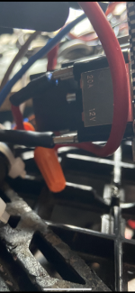
Starter Motor / Solenoid / Relay

bob58o

SuckSqueezeBangBlow
Messages
9,646
Reaction score
1,859
Location
Chicago-town USA
How do I make it go whirl?

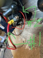
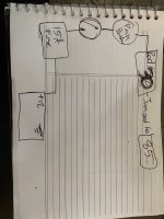
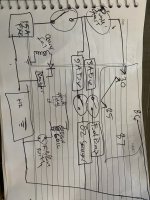
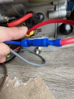
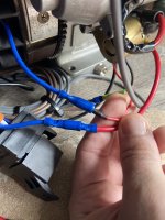
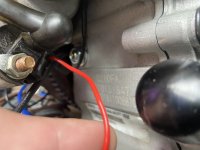
The larger red wire marked #1 gets 12v when I flip main switch on.

The smaller red wire marked #2 gets 12v while I hold the push start button.

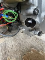
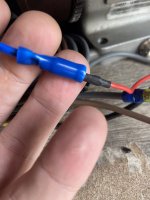
Is that smaller red wire going to the solenoid where I want to connect the blue wire from the relay?

That’s how I have it hooked up now, but no spin spin.
 

Attachments

  • IMG_4303.jpeg
    IMG_4303.jpeg
    847.6 KB · Views: 14
  • IMG_4297.png
    IMG_4297.png
    412.9 KB · Views: 17
  • IMG_4304.png
    IMG_4304.png
    1.2 MB · Views: 14
Functional Artist

Well-known member
Messages
5,654
Reaction score
3,293
Location
Toledo, Ohio
I think the sm. red wire goes to the 12V+ on the relay (& must conn a neg (-) too)
...then, the blue wire goes from the relay, to the starter solenoid

When, you push the starter button, the "signal" goes thru the sm. red wire, to the relay
...which tells the relay to turn on, or send power, thru the blue wire, to the starter solenoid
...& it should go spin, spin :thumbsup:
 

bob58o

SuckSqueezeBangBlow
Messages
9,646
Reaction score
1,859
Location
Chicago-town USA
Thanks for the reply.
Electronics scare me and I spent a good deal of time researching how to connect everything.

Yesterday I was just moving ground wires around and blew a few of the 15amp fuses I installed.

I think the relay makes a quiet click. I think the solenoid makes a louder click.

The way I have it now I can turn on/off the fuel pump, on/off the O2 sensor,….

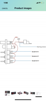
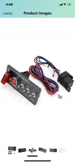
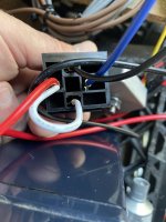
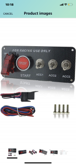
Im not sure about the run/kill switch yet. I may not be getting spark since I moved a ground wire. I’ll tinker around and draw up a diagram if I can’t get it to work. A comment on the Amazon site said this white wire is incorrect. Something about connecting positive and negative side of the relay allowing high current feedback. I don’t know what that means, or if he was correct.

The starter motor works when I jump it.
 

Attachments

  • image.jpg
    image.jpg
    1.7 MB · Views: 4

Functional Artist

Well-known member
Messages
5,654
Reaction score
3,293
Location
Toledo, Ohio
FYI"
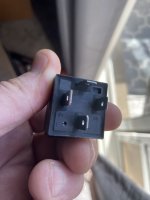
Most (4) pin relays are wired:
85 When you activate your switch it sends 12+ power to this pin
86 This pin is where the ground (-) is connected (completes the circuit so, the relay can function)
87 This pin is connected to the component to be switched on (solenoid)
30 This pin supplies the current, to power, the component

Here is a simple diagram :thumbsup:
https://i.pinimg.com/736x/81/91/c1/8191c12ef792e5d61f075e87dfefc639.jpg
 

bob58o

SuckSqueezeBangBlow
Messages
9,646
Reaction score
1,859
Location
Chicago-town USA
FYI"
Most (4) pin relays are wired:
85 When you activate your switch it sends 12+ power to this pin
86 This pin is where the ground (-) is connected (completes the circuit so, the relay can function)
87 This pin is connected to the component to be switched on (solenoid)
30 This pin supplies the current, to power, the component

Here is a simple diagram :thumbsup:
https://i.pinimg.com/736x/81/91/c1/8191c12ef792e5d61f075e87dfefc639.jpg
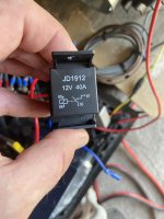
Thank you. I’ll play around with the relay a bit later. I still have to look at the charging circuit too. I have a 3amp single wire magneto but don’t remember if I kept the 1/2 wave rectifying diode in line before the voltage regulator. My understanding is that the diode turns the AC from the coils to pulsing DC, so the regulator never sees AC. This is how I can use a single wire magneto (grounded to block) with a 2-wire (DC-DC) voltage regulator in-line going back to +12 on the battery

I should have just kept using the clone key switch box.
 
Last edited:

Snaker

Active member
Messages
341
Reaction score
183
Lots of unknowns here.
I initially thought you had a electric motor there based on:
Electric project section.
Diagram showing 12v-, that's more typical to some sort of polarity switching of a electric motor. Think the button on hand drills to change directions.
"To starting motors", suggests multiple motors
Later on I see different.
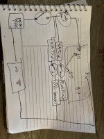
So:

1. The 12v-. Are we talking a simple ground?
If so, that would be designated like so, upside down Pine tree or spelled gnd:

l
l
_____
____
_

2. The device at the top right, is that the relay or the solenoid (a bigger relay) ?
If relay, then its output becomes the solenoid control input (the small red wire)
The relay output becomes the solenoid input.

? why is the relay needed? some interlock circuit?

3. The relay is two circuits, a control circuit that switches the relay on/off
And the switched circuit, what the relay is controlling (the solenoid)
You have to verify hot and ground for the control circuit and input/output for the switched circuit.
The diagram is missing the 12v+ switched current input.
Likely that the main switch output should have a heavy wire going to that relay.

And then you have what appears to be a built wire harness.
Hard to say what has been done for you and what you still need to do.
Can you incorporate that harness into your diagram, making it clear what is wire harness?

4. The white wire? That came out of nowhere. What's it for?
 
Last edited:

bob58o

SuckSqueezeBangBlow
Messages
9,646
Reaction score
1,859
Location
Chicago-town USA
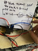
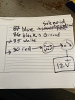
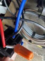
87 is blue
86 is black
85 is white and jumped to 30
30 is red and goes to push button switch and then to toggle switch, then to +12V battery.

Ok so the blue wire should go to this threaded terminal on the solenoid?

And the small red should go to 85? Or 30? Is that jumper wire correct the way it came?
 

Attachments

  • IMG_4314.jpeg
    IMG_4314.jpeg
    1.5 MB · Views: 5
  • IMG_4316.jpeg
    IMG_4316.jpeg
    1 MB · Views: 4
  • IMG_4318.jpeg
    IMG_4318.jpeg
    2 MB · Views: 4
  • image.jpg
    image.jpg
    2 MB · Views: 4
  • IMG_4317.jpeg
    IMG_4317.jpeg
    921 KB · Views: 4
  • IMG_4319.jpeg
    IMG_4319.jpeg
    1.9 MB · Views: 5

Snaker

Active member
Messages
341
Reaction score
183
87 is blue
86 is black
85 is white and jumped to 30
30 is red and goes to push button switch and then to toggle switch, then to +12V battery.

Ok so the blue wire should go to this threaded terminal on the solenoid?

And the small red should go to 85? Or 30? Is that jumper wire correct the way it came?

Yeah, it sounds right as described.
The white jumper applies the 12v from the switch to both the relay control circuit and the relay switched input circuit.
The small red, coming from the start switch, can go to either 85 or 30, chefs choice. the white jumper ties them together as one.
 
Last edited:

bob58o

SuckSqueezeBangBlow
Messages
9,646
Reaction score
1,859
Location
Chicago-town USA
The 12V- was instructions from the Chinese Amazon product that misspelled the #3
 

Attachments

  • IMG_4321.png
    IMG_4321.png
    1.8 MB · Views: 2

bob58o

SuckSqueezeBangBlow
Messages
9,646
Reaction score
1,859
Location
Chicago-town USA
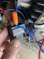
So now I have the blue (87) going to the screw terminal on the solenoid.

The small red wire on the solenoid I have going to the white wire which jumps 85 and 30.

Let’s see if it works
 

Attachments

  • IMG_4323.jpeg
    IMG_4323.jpeg
    1.9 MB · Views: 2
  • IMG_4324.jpeg
    IMG_4324.jpeg
    1.6 MB · Views: 2

bob58o

SuckSqueezeBangBlow
Messages
9,646
Reaction score
1,859
Location
Chicago-town USA
It started to move then blew the fuse. The high current should only flow from the solenoid to the starter motor, right?


Ive gone through (2) 15A fuses, then (2) 10A fuses.

Electronics are the worst. Lol
 

Attachments

  • IMG_4328.jpeg
    IMG_4328.jpeg
    1.1 MB · Views: 0

Snaker

Active member
Messages
341
Reaction score
183
If I understand right. the blue wire replaces the small red wire at the solenoid and the small red wire is out of the picture.
Don't know what it is connected to at the other end?
Your diagram shows you getting battery power through fuse, main switch and start switch
So, no small red wire from solenoid. Disconnect it, tape it off and retry.
 

Snaker

Active member
Messages
341
Reaction score
183
How do I make it go whirl?

The larger red wire marked #1 gets 12v when I flip main switch on.

The smaller red wire marked #2 gets 12v while I hold the push start button.

Is that smaller red wire going to the solenoid where I want to connect the blue wire from the relay?

That’s how I have it hooked up now, but no spin spin.

Wait a minute.
The later photo looks like your splicing the blue into a larger red going to a large solenoid terminal?
The blue should be going to the small red that does NOT go to a large terminal.
Like in this photo
And isn't the red #1 coming from the battery + terminal?
Is the biggest red with black boot going directly to starter?
 
Last edited:

bob58o

SuckSqueezeBangBlow
Messages
9,646
Reaction score
1,859
Location
Chicago-town USA
Wait a minute.
The later photo looks like your splicing the blue into a larger red going to a large solenoid terminal?
The blue should be going to the small red that does NOT go to a large terminal.
Like in this photo
Ok, so the blue (87) goes to the small red wire on the solenoid.
Then do I have to connect the screw terminal on the solenoid to the + on the battery?
 

bob58o

SuckSqueezeBangBlow
Messages
9,646
Reaction score
1,859
Location
Chicago-town USA
I swapped these two wires. I put a 7.5amp fuse in there.

so now the screw terminal on the solenoid should be getting 12v from the white wire (30 jumped to 85).
And the small red wire goes to blue wire (87).

Let’s give it a go.
 

Attachments

  • IMG_4334.jpeg
    IMG_4334.jpeg
    1.6 MB · Views: 2
  • IMG_4330.jpeg
    IMG_4330.jpeg
    2.2 MB · Views: 3
  • IMG_4331.jpeg
    IMG_4331.jpeg
    1.3 MB · Views: 2
  • IMG_4332.jpeg
    IMG_4332.jpeg
    1.5 MB · Views: 2
  • IMG_4333.jpeg
    IMG_4333.jpeg
    2.7 MB · Views: 2

bob58o

SuckSqueezeBangBlow
Messages
9,646
Reaction score
1,859
Location
Chicago-town USA
So it works for now.
IGNITION was set to kill.
I ran out of 5-25 Amp fuses, so there’s a 30 Amp fuse in there. Now sure if wired right, or just have a fuse large enough to make it work incorrectly.
 

bob58o

SuckSqueezeBangBlow
Messages
9,646
Reaction score
1,859
Location
Chicago-town USA
Well it works with a 30 Amp fuse.
It blows with a 4 Amp fuse.
Maybe I’ll upgrade from 12g to 10g wire.

I’ll check for spark now.
 

bob58o

SuckSqueezeBangBlow
Messages
9,646
Reaction score
1,859
Location
Chicago-town USA
Does this 20A just mean it can handle a max of 20A?

Haven’t tested the charging yet, but everything else seems to work when I have a 30A fuse in there.
Have spark on Run, No spark on Kill.

Any idea how many amps this should pull. I think the normal key switch box only used a 5amp fuse (might be wrong)?
 

Attachments

  • IMG_4346.png
    IMG_4346.png
    4.2 MB · Views: 2
Last edited:
Top