Solenoid pulse controller

Status
Not open for further replies.

Ebrownie

Member
Messages
582
Reaction score
1
Location
Western Montana
So my snowmobile is a polaris 600 with an aftermarket turbo. Because the engine is a two stroke, you have to have a separate oiling system for the turbo since there is no engine oil in the crankcase. The turbo is a Garrett GT2860RS I believe. It is a ball bearing turbo so it does not need highly pressurized oil like a journal bearing turbo needs.

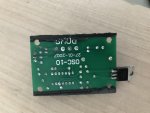
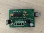
So recently my oil pump for my turbo quit working. After taking stuff apart and some research, I found that my pump is a Gotec emx 08-t/n. It is a 12v liquid pump, draws 1.5 A max. The pump works with an electromagnet and pulsed electricity which moves a piston back and forth. So if you hard-wire it to 12v dc, it does nothing. Because of this, the pump has a controller, which is a little circuit board that puts out pulsed dc at 50 hertz. Correct me if I’m wrong, but I believe it is also square wave, which is a 50% duty cycle? So it puts out a low frequency wave to quickly pulse the pump.

So the pump still worked fine when I hooked it up to a battery, but the controller is no longer functioning. No voltage comes out of it at all. I looked it up and found that the controller is a Clark PD-106, and it is meant specifically for gotec solenoid pumps. The problem is I can’t find a place where I can buy a new one.

I have been looking for a controller that could replace it, but I have not found one yet that seems to be a good match. There are plenty of pulse width modulators, but all of them are for dc motor rpm control and their frequency is way too high. I have found ones that you can adjust the frequency low enough, but they can’t handle more than 50 mA. So basically I need a controller that can handle 2 amps and that has an output frequency in the 20-100 hertz range.

A few of you guys are way more electronically savvy than I am and I was hoping someone could help me out with a solution.

http://www.gotecpumps.com/multimedia/docs/2009/06/EMX_08_-_Technical_data.pdf

https://www.clarksol.com/wp-content/uploads/2016/08/PD-106.pdf

First link is the pump, second is the controller circuit board.
 

itsid

Moderator
Staff member
Messages
11,564
Reaction score
116
Location
Ruhrpott [Germany]
that controller is a pretty straightforward pcb.. no fancy stuff on there..

Sooo if it's not physically broken (which indeed is difficult to fix for most home-users)
every part can simply be desoldered and replaced.
apart from maybe the 14pinner.. I can't identify it on the pic I see so I can't verify that one to be as simple to replace as all the rest.

My guess:
it's just the large cap that bubbled out and is no longer functional.
the pulsing is forwarded through the two transistors , I doubt they see a huge load at all (they're not even on a heatsink)
sooo I highly doubt they cooked off..

So yeah, check what's wrong with the controller and I'd guess that you can fix yours within 5 bucks (incl shipping of parts likely ;))

'sid
 

Ebrownie

Member
Messages
582
Reaction score
1
Location
Western Montana
Here are some pics of the one I have right now. I’ve just never done any repair or work on circuit boards but I do have some small soldering tools so I could try. Nothing seems to be obviously broken. I think some water may have gotten in, I’m not sure though.

Now that I look at it, mine is slightly different than the one on that pdf. I’m not really sure what all of the little things are. What is the large cap?
 

Attachments

  • B42F24C4-C528-4DD3-B353-61DCB95A1B3B.jpg
    B42F24C4-C528-4DD3-B353-61DCB95A1B3B.jpg
    195.1 KB · Views: 11
  • 9C02403C-CD0B-4029-9B1E-B5133A798A48.jpg
    9C02403C-CD0B-4029-9B1E-B5133A798A48.jpg
    257.7 KB · Views: 24

TT540

Newb
Messages
346
Reaction score
1
Location
Huntsville, AL
The cap is the Capacitor which is the tall black cylinder with the shiny silver top. Yours does not look bad. Looks at it from the side. Is the top silver part rounded or flat?

When you say this thing is broken, did you use your multi meter set to measure frequency, or set to measure A.C.? At that low frequency it may show zero on DC.

The output might not be a 50% duty cycle. Perhaps more like 70/30. I suggest this because you said the pump is a piston pump. Those require more power on the pushing than the downward travel. Edit, I read the data sheet and it has a fixed 10ms duration and the trim pot (Phillips screw thing) adjust the dwell or time between on cycles.

That green screw terminal looks dirty. Perhaps the contacts need cleaning?

Can you read any numbers on the black chips?
 

itsid

Moderator
Staff member
Messages
11,564
Reaction score
116
Location
Ruhrpott [Germany]
true c5 looking okay, C1 though.. the smaller one second pic bottom left looks suspicious.

I still can't see the markings on the chip;
If that's proprietary code and it's gone.. there is nothing you can do anyways.

But alright... Everything yellowy-orange is a tantalum capacitor..
highly unlikely to have failed really.. still easy tests first ;)

those and the three electrolytic caps (black cans) tested with a multimeter for continuity at it's leads. or solderspots from below
(none must beep // have a resistance that'd allow for currentflow)

the resitors [stripey] can be tested as well (to have the labelled resistance) but for now just to check again for continuity should do.. (they MUST beep ;))

And last check the diode (must beep in one direction must not in the other)

And that's basically already everything you could easily drytest
if a cap holds it's designed for charge or not requires power of course, so does testing the Modfets and chip. (which we cannot even test if we do not know what it is)

The first thing I would do is: bath the whole board in isopropylic alcohol thoroughly.
clean it with a soft brush (and the alcohol) when clean observe the alcohol flashing off,
that way you can see the traces on the board much better, markings are likely easier to be seen
and most of all.. if there's a crack in one of the bakelite (I know it's not... bakelite :D) parts (the mosfets or the chip)
it should become more apparent since the ipa will creep into the crack and darken it slightly for a short moment even when it's flashed off the surface already ;)
that's why you should watch it go ..

replace everything that you found to be defective with a new identical part,
then everything should be working again... sounds easy, right?

'sid
 

Ebrownie

Member
Messages
582
Reaction score
1
Location
Western Montana
The cap is the Capacitor which is the tall black cylinder with the shiny silver top. Yours does not look bad. Looks at it from the side. Is the top silver part rounded or flat?

When you say this thing is broken, did you use your multi meter set to measure frequency, or set to measure A.C.? At that low frequency it may show zero on DC.

The output might not be a 50% duty cycle. Perhaps more like 70/30. I suggest this because you said the pump is a piston pump. Those require more power on the pushing than the downward travel. Edit, I read the data sheet and it has a fixed 10ms duration and the trim pot (Phillips screw thing) adjust the dwell or time between on cycles.

That green screw terminal looks dirty. Perhaps the contacts need cleaning?

Can you read any numbers on the black chips?

The top of the capacitor is flat. When I say it is broken, I mean that with my multimeter it reads around 4-6 volts coming out, but t doesn’t do anything when hooked up to the pump. Maybe whatever adjusts the frequency for the pump is broken so it is putting out power but not at the correct duty cycle or frequency? I have yet to get the chance to test everything but I have it soaking in alcohol to clean it up.
 

Whitetrashrocker

Inmate #952016
Messages
2,358
Reaction score
140
Location
Southern New Mexico
Your PCB is an older one than the one in the link you posted. The one in the link has smd parts. Yours is more user friendly to repair.

The large caps look like they might have puked on the board. C4 and C5.

But I'd suspect one of the transistors died. If I had a schematic it would be more helpful, but like Sid mentioned it's not a difficult circuit.
 

Whitetrashrocker

Inmate #952016
Messages
2,358
Reaction score
140
Location
Southern New Mexico
You can. Buying them individually, they are expensive. But buying a kit or bulk is the way to go. But if you only are going to do this it's kind of a waste.

Digi-key or mouser is a good start. Amazon also has the kits.

Amazon search "capacitor kit" or resistor kit" they run like 20 bux for an assortment of like 600 pieces.
 

TT540

Newb
Messages
346
Reaction score
1
Location
Huntsville, AL
I went back and read this: So the pump still worked fine when I hooked it up to a battery.
So you connected the pump directly to a 12V battery ? What exactly happened? If it is a solenoid like you say, then the piston should have moved "up" and stayed up. It should not have pumped any oil. If you leave it connected too long, it could burn up the pump's coil. It might be helpful to measure the resistance of that pumps coil. Should be between 1 Ohm and 10 Ohms. It may show open if that Diode in the data sheet is in fact internal to the pump's housing.


I might be able to help on the capacitors by sending one or two. On the side of the cap, find the numbers like: 600uF 25V let us know what those are. we can create the order list for www.digikey.com

For the transistors, those are the two black chips that have three posts soldered into the board. They also have a screw hole on their body for attaching to a case. Did these have screws connecting them to a case? I ask because that's how these transistors sink heat out. Having heat conducting grease helps with that. Doubt this is an issue on a sled though. Anywho, you'll need to find a part number of some kind on these.

I suspect the circuit board you have uses the 14 pin IC to serve as the timing generator and the two transistors are setup in a "push pull" amplifier relationship (think really fast relays). The smaller capacitors effect the timing capability (frequency). The larger capacitors effect the power capability (current/voltage out).
 

Ebrownie

Member
Messages
582
Reaction score
1
Location
Western Montana
Yes, when I hooked it up it just moved the electromagnet. But then I quickly tapped it on and off and it pumped like it should. I may just buy a kit for the parts because I am sure I will use them at some point in the future. It seems like it’s not a bad thing to have around.
 

Denny

Canned Monster
Messages
8,502
Reaction score
4,735
Location
Mayberry, Indiana
I would look at the solder joints first for cracks or corrosion. I see you have plenty of corrosion. Repair that first. Cracked solder joints are more common than you think.

Denny
 

65ShelbyClone

Active member
Messages
623
Reaction score
97
Location
SoCal
Finding a large photo of the newer controller design might reveal what type of chip the 14-pin thing is and what kind of transistors are used.

What does a new controller board cost?

I still can't see the markings on the chip;
If that's proprietary code and it's gone.. there is nothing you can do anyways.

If the markings have been removed, that makes me think it's not proprietary. They grind the numbers off so end users can't easily find a replacement or so it's harder to copy the circuit. I have a junky EEPROM programmer where the Chinese bootlegger obfuscated 93% of the chip IDs because they're just mundane logic chips. Not that the programmer design was actually worth copying though...
 

itsid

Moderator
Staff member
Messages
11,564
Reaction score
116
Location
Ruhrpott [Germany]
frankly chances are it's a mere timer with some voltage comparator
(since I cannot think of anything other being needed really)

But w/o any hints [aka markings] we cannot tell for sure, and whatever it is,
it'll be beyond most users (incl myself most of the days *gg*) to even find out;
much less find a proper replacement for it.
So simply calling it a day and buy a fresh controller is very likely the easier way to fix in case that chip's busted.

'sid
 

Ebrownie

Member
Messages
582
Reaction score
1
Location
Western Montana
I looked around some more and ended up just buying a regular dc brushless pump. It was cheap and doesn’t need a controller board like that solenoid one does. So I will use that for now, but I may still mess around with that circuit board for fun. I took the capacitors off and tested them and none of them read anything for capacitance. So I’m not sure if I’m not testing them right or something, because there’s no way all of them would be toast right?
 

65ShelbyClone

Active member
Messages
623
Reaction score
97
Location
SoCal
I took the capacitors off and tested them and none of them read anything for capacitance. So I’m not sure if I’m not testing them right or something, because there’s no way all of them would be toast right?

Did you try swapping the leads? What kind of meter?

The electrolytic (cylinder-shaped) caps are polarized.
 
Status
Not open for further replies.
Top