Okay cool...
that still looks weird to me..
so I asked the next source I could come up with:
maxtorque..
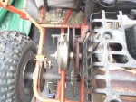
simple reason: they sell a series 20- esque (symmetric) TC with an outboard mounted driven...
And here's what they say in
their instructions:
maxtorque said:
Assembly instructions
Your complete unit must be mounted on parallel shafts with a desired center distance no greater than 6 13/16 (6.8125) inches. After it is centered at idle the driven unit must have at least 3/8 of an inch inward float to properly align with the driver unit.DO NOT USE UNIT WITHOUT COVERGUARD IN PLACE. Pieces may not be interchanged with any non Maxtorque components.
that's a smaller belt than a series 40... but it MUST float *shrugs*
And in fact MFGsupply paint an even darker picture in
their FAQs
an even darker picture...
What are the keys to a proper alignment said:
....If not parallel, the belt will be pulled to the side of the sheave face, creating uneven and damaging side pressures. This wil not let the belt of the system attain either its proper low end or high speed power range. When not parallel, the system will be erratic in its operation from engagement through the highest speed. Belts will wear very rapidly, and the uneven wear pressures will in many cases cause severe wear and damage to the clutch assembly. The damage caused by this can be likened to that created by a bent crankshaft.....
*shrugs*
I don't know.. I'd trust Grant enough to give it a try for exactly ONE belt..
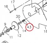
but while doing so, I'd search for a method to move the sprocket to have a floating driven.
Just in case.
Also, just because I would take that risk....
I'm not sure I could confidently tell anyone to do the same.
Sorry Grant; I know I specifically called for your advice, but I just read those websites, and I'm just unsure now.
'sid
 clips.jpg42.8 KB · Views: 12
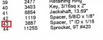 clip2.jpg25.5 KB · Views: 9