Radio Control Off Road Kart

Status
Not open for further replies.

shyflyguy

New member
Messages
44
Reaction score
0
Location
Tulsa, OK
I've never built a go kart, and may have ridden in them all of twice.

I'm working on a project kart that won't have a seat or steering wheel at all! I picked up a nice Futaba 4PLS transmitter and have been sorting out some of the problems associated with trying to control go kart level forces with those dinky little RC servos. I've got the plan sorted out, next up is the execution. The first shipment of parts arrived this week, and now I'm working on simple assemblies while I iron out the details of my frame. I promise pictures as I go along, for now all I have are rough sketches and ideas. Please chime in with ideas on anything and everything here, I'm always open to ideas.

The whole thing is started by picking up a Predator 6.5hp that was $98 from Harbor Freight on sale, and MUCH cheaper than a large RC engine. So far I've got 145/70-6 knobby tires for the rear on a 1" live 32" axle mounted to a subframe that will have 2" of travel in the 12" shocks. The hinge point will be the same center of rotation as the jackshaft in the torque converter thereby eliminating chain length problems while not bouncing the engine all around either. I'm using a 12:45 ratio on #40 chain aiming for 40mph top end. I picked up a GM power window motor to handle the steering since I'd just break an RC servo. I'll be tying it to a Pololu JRK12v12 controller, and power the whole setup with a deep cycle RV or marine type battery. I figure heavy duty RC servos should be enough to handle the throttle and a mechanical disc brake. I'll use a voltage regulator to drop it down to 6v for the RC receiver and other servos.

The current running debates are as follows:

Front Suspension:
I'm torn between double A-arm or J/trailing arm (yes for a front suspension). I'm pretty certain the double A is more sturdy/beefy, but is also more complex and likely heavier. The J/trailing arm is simpler, keeps the rotation within the vertical plane without the camber concerns of A-arm. Of course with only 2" of travel on the 12" shocks and 4.10x3.50-4 knobby tires I'm not sure camber is even a concern? Right now I'm favoring simplicity even though I just found a great post for an A-arm steering setup.

Tubing size:
Square tube, considering 14ga 1" or 1.5". Since there's no person riding on the cart, I figure we get to lose 250lbs from the stress. But stress will be added driving rougher via radio control and off road. The added weight of the 1.5 tube should help increase weight and traction, and since I'm dumping my large rear off the kart I can afford the heavier studier frame. Of course smaller is cheaper and easier to figure into design. Leaning towards 1.5" anyway, it's only money, and a little extra math to build something that will end up being indestructible!
 

shyflyguy

New member
Messages
44
Reaction score
0
Location
Tulsa, OK
Day 1

We'll call today Day 1, because even though I've been sketching, thinking, and drawing for weeks, today's the first day I actually physically did something. To start, of course unpack everything that arrived. Of course I'm going to have to put in subsequent orders, but the idea of this was simply to get the bulk of things in to start taking measurements to design with. And of course test fitting parts together.


I had lunch out, and dropped off the rear rims, tubes, and tires at the local tire shop to be mounted. I'm sure I could do it myself, but they don't charge anything so why not? Unfortunately I apparently got the wrong tubes for split rims, which require 90 degree valves. They'll have them done in the morning with the right tubes. I also found out that there's no local shop that knows what keystock is, and only found one place that sells #40 chain. I don't think I'll need 10 feet ($12 Atwoods) but since that's the only way to buy it, maybe I'll incorporate some instead of throttle or brake cable. There's also no place to obtain locking collars that I forgot I might need. I did manage to grab some lock washers and nuts to fit the wheel hubs at Lowe's, 5/16-24.

Upon returning home I set poured oil and gas into the engine and gave it a yank, then another, and another. Turn OFF switch to ON position, yank again, fires and runs. Turn off and set about installing the torque converter onto the engine. This proved more difficult than I thought. The bolts provided in the torque converter kit probably work fine for most engines, but remember I went cheapskate with a Harbor Freight Predator engine. So the bolts fit, but the thread pitch is wrong. It took about 15 minutes of online searching to find what the right size was, and made another trip back to Lowe's (1mi) for the 5/16-24 1" bolts. Search results also turned up that many people use a 3/4" washer for spacing on the driver side of things with the Predator engines, so grab some of them too. Get it all home and try installing the backplate again, but it keeps hitting something. Find out it's the second oil filler cap (why are there 2?) and make quick work of the plastic grip on the bench grinder. Remainder of attaching backplate installs just fine with correct pitch bolts.


Now the torque converter initially came with a #41 10T sprocket, and because I'm after top end I bought a replacement 12T sprocket. Murphy's law says nothing is so easy as a simple pull 10T off and put 12T on! The 12T sprocket was not quite to spec, and required a little filing to widen out the center bore. Of course I also had to file down the key stock a little bit as well since I didn't have a file small enough to address the undersized keyway. Fix all that, and SECURELY install on the jackshaft. I regretted the securely part after about an hour of trying to figure out why the driver and driven didn't align. It wasn't until I compared the 10T sprocket to the 12T sprocket that I realized the hub was wider on both sides of the 12T sprocket. An hour of swearing, grunting, and one loud yelp (missed punch with mallet, hit thumb instead) ensued while attempting to tap, pry, wiggle, and beat the keystock out of the sprocket keyway and get the still slightly undersized 12T sprocket back off of the jackshaft. Finally get it off, reward myself with a beer and briefly debate about sanity. Most sane people would figure that a 10:45 ratio would be fine, but I spent money on that sprocket so I was going to make it work. Cue an hour of work on the angle grinder and bench grinder to shrink down that hub to roughly match the size of the 10T. Of course now I've littered the inside bore with all sorts of crap and have to file that out again. Now it fits on a little better, and the belt lines up pretty much like it should. Subbed a washer on the driver out for a lock washer and everything else is fine.


Called it a night since it was getting cold fast in the workshop and headed back inside to write this lovely post and start putting together another order. I'll grab the rear tires tomorrow, but it looks to be too cold to spend much time in the workshop, so I'll spend the day doing laundry, cleaning house, and drawing up designs.
 

shyflyguy

New member
Messages
44
Reaction score
0
Location
Tulsa, OK
I just went back out to the shop where I'd left my cell phone and half a beer, and smelled fuel. I discovered that the fuel tank is leaking at the seam of the front left corner near the torque converter. Thankfully I still have the receipt, and it's within 90 day warranty. Looks like I get to take this all apart and make a trip into the city tomorrow. :( Not what I wanted to do with the last day of my weekend.
 

firemanjim

Just kartin' around....
Messages
5,247
Reaction score
83
Location
Houston Texas
You know, you COULD find away to attach a seat, eventually, and be able to ride this thing. After all this work, I'd rather ride than watch......
 

shyflyguy

New member
Messages
44
Reaction score
0
Location
Tulsa, OK
Subaru Commercial

Your comment made me think of that! Actually it's been a consideration for a little more than the past week whether to build a go kart I could drive, or stick with the big RC off road buggy idea. I took a poll of coworkers who've had to listen to me talk about this and various design variations for weeks now. Surprisingly more came back with the response for RC over a kart. A couple of them have karts and still jumped on the RC bandwagon. The argument seems to focus on the fact that there are plenty of people with karts, but this would really be a one of a kind RC buggy.

The radio is rated for about 1200ft effective range. I plan on driving it around the field at work, occasionally from the catwalk of a 200ft high tower with a friend on the ground to help me if I get stuck, roll over, engine stalls, etc. It's also a motivation to get my large behind to walk around the neighborhood at home more often harassing the octogenarians and little yappy dogs!

That's not so say there might not end up a place to sit on top of the engine for leisurely drives at some point once the kinks are all ironed out. Of course if the whole thing ends up being a bad idea, or I never can get the motor-servos to run properly, I can abandon the RC idea and just modify it back to a go kart. Of course if I make it so that I can drive it, I'll still end up just watching it get driven by my niece and nephew. If I have a seat on an RC there's no way their mom would let them ride while I drive, LOL!
 

Hursty

VOX NIHILI
Messages
197
Reaction score
0
Location
Denver PA
Subaru Commercial

Your comment made me think of that! Actually it's been a consideration for a little more than the past week whether to build a go kart I could drive, or stick with the big RC off road buggy idea. I took a poll of coworkers who've had to listen to me talk about this and various design variations for weeks now. Surprisingly more came back with the response for RC over a kart. A couple of them have karts and still jumped on the RC bandwagon. The argument seems to focus on the fact that there are plenty of people with karts, but this would really be a one of a kind RC buggy.

The radio is rated for about 1200ft effective range. I plan on driving it around the field at work, occasionally from the catwalk of a 200ft high tower with a friend on the ground to help me if I get stuck, roll over, engine stalls, etc. It's also a motivation to get my large behind to walk around the neighborhood at home more often harassing the octogenarians and little yappy dogs!

That's not so say there might not end up a place to sit on top of the engine for leisurely drives at some point once the kinks are all ironed out. Of course if the whole thing ends up being a bad idea, or I never can get the motor-servos to run properly, I can abandon the RC idea and just modify it back to a go kart. Of course if I make it so that I can drive it, I'll still end up just watching it get driven by my niece and nephew. If I have a seat on an RC there's no way their mom would let them ride while I drive, LOL!


If that is a 2.4ghz transmitter, you probably have more than a 1200ft range. I used traxxas an Venom 2.4GHZ Transmitters. they worked as far as i could still see my vehicle and what it was doing.
:cheers2:
 

shyflyguy

New member
Messages
44
Reaction score
0
Location
Tulsa, OK
Day 2

Last night I placed a couple more orders for overlooked things like locking collars, a brake caliper, a couple heavy duty servos (160oz-in) for brake and throttle, and the all important motor controller.

Today I had fun (sarcasm) with the exchange to Harbor Freight. They wouldn't take it back with fuel in it. So I made it empty (don't ask), and then spent a couple hundred dollars more on other things I "needed" for the workshop. I swear I can never have a trip where I spend less than $250, such an evil but frequently useful place. In the end I walked out with a replacement engine, and aside from the gas they didn't seem to care what condition the return was in.

I grabbed the tires from the shop, they took a few minutes extra and made my tubes work instead of ordering new ones. Customer service is the biggest reason I continue to use this shop! Of course with every little bit I get excited about having parts to look at together and have to test fit things. Looking at the below layout I realized this won't be as wide, and will be longer than originally anticipated.

I could of course shorten the whole thing up eliminating the suspension. The shocks I ordered fit the rear of a Yerf Dog and apparently have a reputation for being stiff. Hence they are entirely too stiff for a cart that's basically engine and frame only. So I've listed them on eBay and am searching for other options. So I'm looking for input here, do I leave the suspension out even though I primarily plan on driving off road? Of course if you can provide any suggestions on shocks please let me know! I figure the whole cart will weight about 200lbs: 45 engine, 60 frame, 80+ battery. Please chime in with ideas/suggestions!


chancer

ɔ ɥ ɐ u ɔ ǝ ɹ
Messages
9,358
Reaction score
83
Location
COMFORT, TEXAS
Definitely put a seat in this thing. Then you can charge for rides. Besides your nieces and nephews mom will not ALWAYS be around.
As far as suspension. If it is just remote control I would leave it off. It is not like you need a cushy ride there is no occupant. Or Scan through this build "Micro Suspension" Valve springs. http://www.diygokarts.com/vb/showthread.php?t=21076
 

shyflyguy

New member
Messages
44
Reaction score
0
Location
Tulsa, OK
Are those HF dolly wheels??

I assume you mean these? No, I've read that those aren't good for standing up to much. I'm planning to beat the crap out of this thing for years, so while I could have picked the HF trolley tires cheaply, instead I got 4.10/3.50-4 with tubes. BMI actually had them with the hubs and bearings already installed for cheaper than I could get all the pieces.

PS- I have no idea why I just called them trolley tires.... I'm a red blooded gun toting steak eating American, that should have been dolly or hand cart tires!
 

landuse

Moderator
Staff member
Messages
18,743
Reaction score
511
Location
Pietermaritzburg, South Africa
I assume you mean these? No, I've read that those aren't good for standing up to much. I'm planning to beat the crap out of this thing for years, so while I could have picked the HF trolley tires cheaply, instead I got 4.10/3.50-4 with tubes. BMI actually had them with the hubs and bearings already installed for cheaper than I could get all the pieces.

PS- I have no idea why I just called them trolley tires.... I'm a red blooded gun toting steak eating American, that should have been dolly or hand cart tires!

Just checking!! :thumbsup:

And they arent hand kart tires, they are trolley tyres... :D:D
 

shyflyguy

New member
Messages
44
Reaction score
0
Location
Tulsa, OK
Suspension musings....

I'll not be actually accomplishing any physical work on this until at least the middle of next week, as I work weekends and my days off are Wed/Thu. But with snow on the ground, and more forecast to fall over the next 3 days (Snow-pocalypse Oklahoma), I'll have lots of time available for the design ideas to roll around. These goofy flat-landers have no idea how to handle even a dusting of dry snow. It's weather like this that makes me proud to be that crazy :censored: yankee flying past everyone. It also makes me miss how the snow was properly dealt with and people knew how to drive, but I digress.

Today I repeatedly sat down and mulled hard over the suspension issues which have arisen. As previously stated the shocks I ordered are too stiff to even try using. I can't compress them no matter how hard I try. Anyone need some stiff 12" shocks that fit Yerf Dogs?

I looked extensively online for small lightweight shocks for about 90 minutes before giving up and seeing what else I could find. Great thanks to Chancer for suggesting this post for simpler ideas. I thought about the valve springs that were removed from my '92 Ford Bronco a few years back when I helped a mechanic rebuild it, and decided they were both too short, and probably not properly rated for my application. While they work for the previously seen cart, I'll not have the weight of a driver, and I want more suspension travel as well for the off road reason. I no longer have the old springs and bi-weekly regret selling that Bronco.

So I briefly considered some very lightweight but large (2.5x12") automotive springs from Summit Racing, until I found Century Springs. Their company website basically states that if they don't have the spring you need in stock, they'll make what you need for you! Although their selection of springs is absolutely astoundingly massive, so I doubt it will come to that. I've got a few measurements to work out before figuring just which springs I need, and I'm still working on suspension designs. I know this forum is big on pictures, so I'm sorry but no pictures as all I have are rough drawings on paper. I'm a horrible artist, but if I get enough time I'll see what I can do. In the mean time please use your imagination.

To encapsulate the springs I'm thinking about just a simple guide rod welded to the bottom frame and free sliding through a bushing in the upper frame. The upper and lower frame will provide the surface to hold the spring in place, and I'd use a nylon locknut at the top as a stopper to prevent the guide rod from falling out due to over-extension. I might use a spacer inside the spring to prevent compression to solid length if required.

I'll have to revisit the rear suspension design, but I'm still thinking a trailing arm. I no longer have a 12" shock to deal with, and the previously described spring/guide rod setup will end up being much shorter like less than 5". This changes things. The previous outside the frame trailing arm design won't work because it can't be cross braced without interfering with the ladder frame. That would result in more of an independent type suspension on a straight axle and the associated torsional stress applied to the bearings (as they are the connecting point to the trailing arms). Since I'm using bearing hangers instead of pillow blocks, and spring travel will ideally be 2" or less, this may or may not actually be an issue. I also have to consider the possibility of impact of the drive sprocket (7-7/16" OD) on the rear cross bracing of the ladder frame. Moving the trailing arms inside the ladder frame means raising the cross braces above the frame where they don't work as well. I think this will also leave too much space on the axle between the wheel hubs and the bearings (support from frame). It's a 1" solid axle, but I'm sure it's still best to have then hangers mounted as close as possible to the wheel hubs. I'll be reconsidering this entire design and it's implications and problems over the course of this weekend at work. :mad2:

:idea2: 
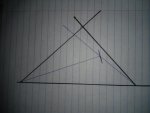
Here's the good news, the front suspension design that came to me today. It's somewhere close to a MacPherson Strut. Lower A-arm mounted normally with hinge point at the lower backside of the spindle bracket. A small T frame welded above the spindle bracket hinge joint to the backside of the spindle bracket. The top of the T will form the lower retainer/mount for the previously mentioned spring assembly, mounting the top of the T lower might interfere with the hinge movement of the A-arm. Spring assembly with guide rod bottom on top of T, and top goes through a strut bar across and probably above the ladder frame to spring assembly and guide rod for other side. Because the A-arm is hinged at both sides it should eliminate the camber changes that would be associated with a single A-arm design. The use of the spindle bracket and spindle keeps steering like most karts, and doesn't add rotation into the spring assembly. Here the guide rod also functions to keep the movement of the spindle bracket vertical. I've been looking for flaws and drawbacks of this design all night, but maybe someone with fresh eyes can provide a different perspective. Well as best as one can without having a diagram! I guess technically I could eliminate the spindle bracket and use a very long bolt and spring to get up to the strut bar. I don't think that would be as strong, but it's 2am and I'll throw that idea in the bucket to consider tomorrow.

Like always, please feel free to chime in with ideas and suggestions!
 

Poboy kartman

Senior Moments Member
Messages
12,461
Reaction score
63
Location
White Settlement Texas
I'm not sure exactly how you plan on using the spring/rod/bushing contraption, but I think there is a minor flaw as described..... "rod welded to frame bushing at top....

I like the idea and think it's cool,...but if you are using it on a pivoting rear end....it will bind and not work....

If you look at the popsicle sticks in the pictures...notice how the angles change....so...the bottom of the rod (where it attaches to the frame) ...needs to be able to rotate like the hands on a clock....so maybe a bolt welded to the frame...then a heim joint bolted on it, then a spring cup welded to the rod that is threaded into the heim.....

Then the bushing at the top needs to be able to rotate 90° to the rod hole.....(like a bolt that goes through the frame and is tapped into the side of the bushing) .....

Make sense?????
 

Attachments

  • 14251232192530.jpg
    14251232192530.jpg
    77.3 KB · Views: 8
  • 14251232424891.jpg
    14251232424891.jpg
    64.8 KB · Views: 7

firemanjim

Just kartin' around....
Messages
5,247
Reaction score
83
Location
Houston Texas
Shocks from a Honda z50 work real nice. Not too soft, amazingly just enough for me, and my kart with engine. Only 1" sag when I get in, then I have to JUMP on it to make it bottom out......
 

shyflyguy

New member
Messages
44
Reaction score
0
Location
Tulsa, OK
@Poboy Cartman
You're absolutely right! That never would have worked without modification. I looked a little closer at why it seems to work with the described front suspension and I think it's because of the 2 hinge points there. Effectively the front suspension triangle allows me to change 2 angles (pivot points at each end of A-frame) and the length of one side (compression along the spring guide). The previously stated rear design had only one angle change and would have forced an angle change at the weakest point, the guide rod at the bushing quickly wearing away the bushing. This has an easy fix though, put the bottom of the guide rod on a piece of square tube inside of the trailing arm frame, mount with a single bolt. That gives the hinge point for rotation, and also makes the alignment with the ladder frame a breeze. Thank you for pointing this out! I'll still have to work on the design I like for cross bracing and interfering with the rear sprocket, but with another 1+" of snow since my last post I'll have plenty of time at work tonight!

@FiremanJim
I'll take a look into those, thanks.

@Chancer
I know that was a book! Sorry about that, but I wanted to describe in as much simple detail as possible the layout, since I didn't have a diagram or picture! A picture is worth 1000 words.... proof validated! Ok so I really am too much of a math and science type of guy.
 

shyflyguy

New member
Messages
44
Reaction score
0
Location
Tulsa, OK
Ok here we go with a few bad sketches. I've looked again at the rear suspension and figure a differently shaped trailing arm frame mounted inside of the ladder frame does what I need. By eliminating the rear most cross brace on the ladder frame I no longer have to worry about sprocket or brake disc impact. The redesigned trailing arm frame ensures cross bracing is adequate and shouldn't cause stress on the bearings. It would be simpler to have the spring assembly between the two frames but I couldn't find a way to allow it to rotate preventing binding at the bushing. So instead a small piece of square tube bolted to the trailing arm frame allows rotation, and a similar piece welded in place at the inside of the ladder frame fixes the top spring and holds the guide rod in place. The angle of the trailing arm frame even at full spring compression should not impact the ladder frame cross brace just in front of the spring assembly. Ok no more words, here's the sketches.


Poboy kartman

Senior Moments Member
Messages
12,461
Reaction score
63
Location
White Settlement Texas
This is a little visual that should help show the dynamics at hand.....in marker is the original set-up.....note the angle on the upper is 90° ....the ballpoint line represents the same length and angle arm.....

So you can see why both ends need to pivot and in which direction.....
 

Attachments

  • 14252539729690.jpg
    14252539729690.jpg
    63.1 KB · Views: 4
Status
Not open for further replies.
Top