Project Stoopid!

Master Hack

Well-known member
Messages
4,136
Reaction score
6,564
Location
Mountain top Labratory
Meanwhile back at the shop...
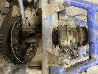
This shaft drive thing is looking like it could work.
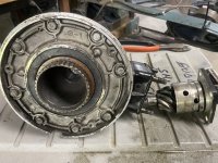
So here is the guts of the rear wheel/differential/gearbox/propulsion unit/thingy.
The bore will accept a 1" axle shaft without much work. I'll need to make a heat treated shaft. I don't think a mild steel shaft 1" diameter will last too long, handling 110HP.
Other than that this looks almost easy. Yeah, don't quote me on that.
IMG_4945.JPG
 

panchothedog

Well-known member
Messages
2,788
Reaction score
3,740
How you gonna hold the wheels or hubs on that axle. 1" with 1/4" keys doesn't sound like it's up to digesting 110hp. Neither part. The axle or the keys. Although
I am ready to admit I don't know anything about how much more strength the heat treating process will ad to the axle. And I bet that you do.
 

Master Hack

Well-known member
Messages
4,136
Reaction score
6,564
Location
Mountain top Labratory
How you gonna hold the wheels or hubs on that axle. 1" with 1/4" keys doesn't sound like it's up to digesting 110hp
Thats a good point. I'm exploring the possibilities there. The center section where that R & P go is only about 14" long. I may just weld that into the gear carrier. Another possibility is there is a flange (not pictured) that slips over the the splined center hub thingy. I'll take that gear carrier apart and see what other dumb ideas I can come up with. I'm open to fresh ideas should any body have one they want to share.
The drive shaft was inside a square tube, it bolts to the flange at the pinion gear and the same at the engine. That part is purdy simple.
Lol you should have known not to say that
I said don't quote me on that! :banana: I know that was a risky statement.
 

Functional Artist

Well-known member
Messages
5,345
Reaction score
2,834
Location
Toledo, Ohio
Another possibility is there is a flange (not pictured) that slips over the the splined center hub thingy. I'll take that gear carrier apart and see what other dumb ideas I can come up with. I'm open to fresh ideas should any body have one they want to share.
Hey T,
I would explore this option
...before tryin' &/or resortin' ta weldin' :thumbsup:

Kinda like how the rear axles (on many pick-up trucks)
...have a flange on the "outer" end (of the axle)
...ta be able ta
...bolt to the wheel hubs ;)

But, kinda different
...&/or/but, kinda the opposite (if ya know what I mean) :p
...& in the middle...not on the ends

Maybe fab up a "hub" (I know a guy) :smartass:
...that has the "flange that slips over the splined thingy" mounted on the outside
...with your 1" axle goin' thru the middle :2guns:
 

Master Hack

Well-known member
Messages
4,136
Reaction score
6,564
Location
Mountain top Labratory
Thats kinda what I'm thinking now.
Here is a photo documentary of the situation...
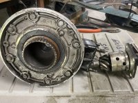
This is the stationary thingy as seen previously on "Hacks Garage"
IMG_4945.JPG

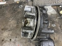
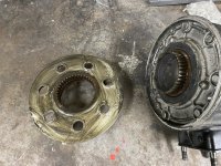
And this is how the spinny thing slides ove the splines. The fin things go into a rubber cushion inside the wheel. Remember the axle is stationary and the wheel turns,
IMG_4949.JPG
IMG_4948.jpg

View this exciting video of the spinny contraption in action.
https://youtu.be/1X7sCeLANic

Extra points if you identify the artist playing in the background.
 

Functional Artist

Well-known member
Messages
5,345
Reaction score
2,834
Location
Toledo, Ohio
Thats kinda what I'm thinking now.
Here is a photo documentary of the situation...
This is the stationary thingy as seen previously on "Hacks Garage"
View attachment 154878

And this is how the spinny thing slides ove the splines. The fin things go into a rubber cushion inside the wheel. Remember the axle is stationary and the wheel turns,
View attachment 154879
View attachment 154880

View this exciting video of the spinny contraption in action.
https://youtu.be/1X7sCeLANic

Extra points if you identify the artist playing in the background.
CCR
 

Functional Artist

Well-known member
Messages
5,345
Reaction score
2,834
Location
Toledo, Ohio
Hey T,

OMG they don't give ya much splines...do they? :huh:
...probably/maybe have to add some additional support :unsure:

So, could ya (off the top of my head)...maybe :idea2:
1.) cut them "fins" off
2.) flip 'er over & mount 'er, on the splines
3.) & then, use them bolt holes, to mount/bolt to your "custom hub", that "fits" on the axle :cheers2:

* Disclaimer:
Always, always, always think 'er thru
...& make sure the idea is even "feasible"
...in your particular situation
...before following...my &/or any...advise :innocent::devil2:
 

Master Hack

Well-known member
Messages
4,136
Reaction score
6,564
Location
Mountain top Labratory
The power transmission, is the biggest hurdle to overcome. The 30sumpthin in the Pile o Scrap caused enough headaches so almost 4x could be a challange.
.
The center section (stationary thingy) looks like l can bore it out to accept a 1.125 shaft maybe even 1.25. That would make fot a much stronger shaft. Then bolt the spinny thing to the hud weldeda on the shaft. and flanges to ends of the center shaft to accept CV shafts.
I'm not afraid of welding something to the shaft
Purdy much the same as i did on the Pile o Scrap.

F6703A3D-F2F0-4D2E-A815-8FF6EA235DF1.jpeg
if l have to get in there for repairs , l'll just cut the shaft andd make another.
 

Master Hack

Well-known member
Messages
4,136
Reaction score
6,564
Location
Mountain top Labratory
Or do you have to have a IRS?
Yeah, it's gotta have IRS. The VW half shafts I used on the Pile o Scrap work really well and should be able to take the heat.
I have a Miata diff, but that a solid rear a believe.and would take alotta work and I dont want the diff part, it needs to be locked soehow.
I don't like getting too normal. My MO is do it different, do it cheap.
With that in mind I'll look at the cross Kart page and see how they do it, then I'll make some weird bast, errr ahhh adaption.
Bottom line is I want to use the Chainless option and IRS and keep it relatively small.
SIMPLE!


WTF did I get myself into?
 
Top