I have a kart I just picked up with a no start. Wiring has been hacked , ignition broke, etc. Just replaced the ignition and rewired... kart turns over but has no spark. I need to verify the wiring to the control unit which then goes to the mag to be sure itss wired correctly... Its a 6 wire, colors include , red, red/white, yellow, yellow/green, black and a smaller yellow wire .. Currently its wired red +, red/white is not connected, black -, yellow/green mag, yellow mag, small yellow ignition key on... Anyone know if this is correct... Also I cant find a wiring diagram anywhere for this... Id like to be able to test it to verify whats the cause of my no start... If anyone knows how to test the coil, magneto and control unit Id appreciate it.... I own a volt meter but dont have any specs on these items with ohm readings.... Thanks in adavance....
You are using an out of date browser. It may not display this or other websites correctly.
You should upgrade or use an alternative browser.
You should upgrade or use an alternative browser.
please please help XTK-710e subaro robin 10hp
- Thread starter mogyver69
- Start date
- Status
- Not open for further replies.
r97
Measure twice cut once
Some pictures of the setup would probably help. Could you try disconnecting everything so the only electrical is the magneto and spark plug? If you do make sure you mark the wires so it goes back together the way it came apart. Are all the grounds good?
Check to make sure spark plug isn't fowled, and that all your switches are in run positions. Also try testing all the wires and switches to make sure there are no shorts, or breaks.
If you go to robinamerica.com, you can download an engine manual, that may have a wiring diagram, but likely not exactly the same as whats on the kart. Try looking through the manuals for this model go kart (I believe its a manco, they have free manuals for download)
Thanks, I went to the robin suburu site and downloaded there service manual, parts manual and owners manual its the ex27 engine . It shows the control module but it doesnt give you color of wires or any wiring diagram and no testing procedures... Just so we are clear I am a Gm certified mechanic and have been a mechanic for over 25 yrs..... The ignition is wired correctly from the key. key on power gives me 12 volt reference from the ignition key to the control module... and acc is wired to lights so we can run lights with the key in the on or acc position... Purple wire is to starter..... The yellow wire runs from ignition switch key on.... I can only assume the wiring to and from the control unit.... Although Im a car mechanic Im not familiar with this ignition system .. what do we need for this engine to run? How does the coil get its power... Im assuming you supply power to the control unit? Im guessing this is a igniter and the flywheel has magnets and a pickup in the manual its called a lamp coil.. When the flywheel rotates the lamp coil builds current and then transfers it thru the magnet to magnatize it... Is this correct... As for the mag I did a ohm reading and found no shorts to ground. I checked grounds and they are good... I have a spark plug boot that the wire end was worn so i cut the end of the wire to reattach but now the wires to short... I ordered a new coil since the wire is part of it.. In the mean time I reattached the boot to the wire and put a plug in the boot and shorted to ground. Still no spark. Maybe Ill be lucky since I had to order the coil anyway but while Im waiting for the part Id like to actually diagnose it rather then guessing..... I will attach pics of what im working on in a fewminutes... Thanks for your help...
Some pictures of the setup would probably help. Could you try disconnecting everything so the only electrical is the magneto and spark plug? If you do make sure you mark the wires so it goes back together the way it came apart. Are all the grounds good?
Check to make sure spark plug isn't fowled, and that all your switches are in run positions. Also try testing all the wires and switches to make sure there are no shorts, or breaks.
If you go to robinamerica.com, you can download an engine manual, that may have a wiring diagram, but likely not exactly the same as whats on the kart. Try looking through the manuals for this model go kart (I believe its a manco, they have free manuals for download)
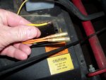
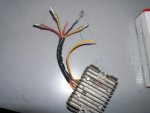
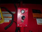
Ok let me back up alittle: From the battery to the ignition I have a red wire battery voltage. I have a yellow wire from the key - ignition on to the engine control unit - see pics. I also have a blue wire from the ignition key on engine start to the starter. I also have a red wire from the battery with inline fuse to the control unit. I then have 2 wires from the magneto (coil lamp). yellow and yellow/red Then I have 6 wires on the control unit - see pics the colors are black, red, red/white, yellow, yellow/green and another yellow smaller gauge wire... Im attaching pics. I have the control unit out right now so Ive taken a seperate pic... The first pic is off the yellow key on power and the mag wires. The second is of the control unit. Theres another showing the ignition key.. The toggle is for the lights. Its set up that when you key on or put the key in the acc position the lights come on and the toggle allows you to turn the lights off . When the key is off the lights will not work..
Attachments
-
 102_2405.jpg71.9 KB · Views: 9
 -
 102_2412.jpg52 KB · Views: 11
 -
 102_2408.jpg85.6 KB · Views: 14
 -
 102_2404.jpg67 KB · Views: 10
 -
 102_2409.jpg72.3 KB · Views: 13
I just rewired, no shorts....And I did recheck.... now im looking to be sure the control unit is wired correctly the 2 yellow wired from the control unit were connected to the mag. The yellow ignition on was wired to the yellow small wire on the control unit . black was to ground, solid red was to bat + and the red with white stripe was not connected... Is this correct... Im questioning the small yellow wire and the red wire with white stripe... Which makes me question everything... lol... Then once this is connected correctly its back to is there a way to test this control unit to be sure its good...????
ok so ive been researching all night. It appears that box with all the wires and the two wires coming out the engine are for running lights and charging the battery and nothing more... If I disconnect the 2 orange wires as there pictured in the pics above the engine should start and run without the box full of wires hooked up... So if I have no spark its one of three items... coil, stator or pickup and or flywheel.... Im still reading.... I read somewhere to connect a volt meter to those 2 wires coming from the engine stator ires gground volt meter and postive to each of the wires one at a time and crank engine with meter set to a/c to see if Im getting voltage from the stator...Is this right?
I wish I could be of some help to you, but I am not an engine guy. Wait a bit and someone will give you some more advice.
Ok let me back up alittle: From the battery to the ignition I have a red wire battery voltage. I have a yellow wire from the key - ignition on to the engine control unit - see pics. I also have a blue wire from the ignition key on engine start to the starter. I also have a red wire from the battery with inline fuse to the control unit. I then have 2 wires from the magneto (coil lamp). yellow and yellow/red Then I have 6 wires on the control unit - see pics the colors are black, red, red/white, yellow, yellow/green and another yellow smaller gauge wire... Im attaching pics. I have the control unit out right now so Ive taken a seperate pic... The first pic is off the yellow key on power and the mag wires. The second is of the control unit. Theres another showing the ignition key.. The toggle is for the lights. Its set up that when you key on or put the key in the acc position the lights come on and the toggle allows you to turn the lights off . When the key is off the lights will not work..
Ok Ive answered my own questions.. This is the voltage regulator and is only for running lights and the battery... With it disconnected the engine should stll run... I found the wiring diagram here http://www.tricountysupply.com/illustratedpartslist.htm and a list of all the parts for my Go Kart... Its the owners manual and theres manuals for just about every go kart made if you go back to there home page... free download....
I wish I could be of some help to you, but I am not an engine guy. Wait a bit and someone will give you some more advice.
Thanks man, I did learn the wiring of the regulator. Its just for the battery and lights... Easy way to know if it works is if your engine runs then its producing ac voltage... Other wise it wouldnt have spark.. So if its running and the regulator is wired correctly, check voltage at the battery ... If its not charging theres issues with your regulator... The parts on $13
Im still working on the no spark issue but I think its the coil... I have no shorts to ground thru the two orange wires and Im reading continuty thru the 2 wires... Thats a good sign.... replacing the coil when the part comes in and rewireing the ignition again... It was wired wrong along with the regulator... Now that I have the wiring diagram I should be able to resolve the wiring issues...
Thanks
- Status
- Not open for further replies.