madprofessor
"Loose Cannon Creations"
Word of knowledge about those RFY gas coilovers..............The nitrogen charge is supposed to stay within a psi range of only a little more than (1) psi (a single psi) difference, don't touch that shrader valve, keep it capped. All of the adjustment is in the adjuster nut on the coilover spring.
If I'm remembering it correctly, there's 2 nuts locking together that you have to knock loose from each other to make the adjustment. Yours should have come with the wrenches (spanners?) to fit that big nut. Definitely smear some Anti-Seez on the threads before you turn the nut under any weight load, they'll start galling out.
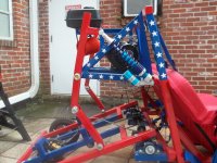
HUGE amount of spring tension adjustment on my 17" long RFY's, see attached pic. Mine came adjusted to max softness, way too soft for my application. Adjustment at least doubled the spring rate, very surprising. NOTE: I felt the nut basically stop turning when there were still several threads left to go even tighter, and I did not force it past that point. I recommend you do the same if you adjust.
If I'm remembering it correctly, there's 2 nuts locking together that you have to knock loose from each other to make the adjustment. Yours should have come with the wrenches (spanners?) to fit that big nut. Definitely smear some Anti-Seez on the threads before you turn the nut under any weight load, they'll start galling out.
HUGE amount of spring tension adjustment on my 17" long RFY's, see attached pic. Mine came adjusted to max softness, way too soft for my application. Adjustment at least doubled the spring rate, very surprising. NOTE: I felt the nut basically stop turning when there were still several threads left to go even tighter, and I did not force it past that point. I recommend you do the same if you adjust.
Attachments
-
 100_0170.JPG2.3 MB · Views: 7