My Yard Kart

NEKrone

Member
Messages
26
Reaction score
26
Location
Michigan (LP) , USA
So I'm hoping this is the best place to post this, If it isn't lemme know. I wanted to just have this thread follow the progress of my yard kart build and to consolidate all my questions along the way here. I got a donated frame that was chopped in half and welded back together to lengthen it. I got it after the chopping. This first picture is how I got it. I will not be driving on the dolly tires. They are there for moral support.
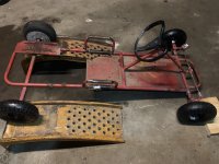
image_50419457.JPG

I plan on using a 32 inch live axle for the rear with 15 inch turf tires. I'm working on removing the paint and I'm going to prime it and paint it with this junk.
paint.JPG

Not sure if the primer is necessary since the paint has primer but I feel like the more things a thing does the less well it does each thing.

The frame will be black and these things below will be red.
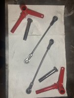
unpainted_red_stuff.JPG

Here is my current progress removing the paint:
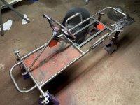
sanded frame.JPG

I added some structure in the center for the seat to mount to. The seat I got was too big to fit between those handlebars on the side so my plan is to add enough support elsewhere to allow me to chop off the handlebars.

Thank you guys for taking the time to check out my post. 😃
 

Rat

Well-known member
Messages
1,750
Reaction score
1,284
Location
SW Virginia
So I'm hoping this is the best place to post this, If it isn't lemme know. I wanted to just have this thread follow the progress of my yard kart build and to consolidate all my questions along the way here. I got a donated frame that was chopped in half and welded back together to lengthen it. I got it after the chopping. This first picture is how I got it. I will not be driving on the dolly tires. They are there for moral support.

View attachment 144230

I plan on using a 32 inch live axle for the rear with 15 inch turf tires. I'm working on removing the paint and I'm going to prime it and paint it with this junk.
View attachment 144231

Not sure if the primer is necessary since the paint has primer but I feel like the more things a thing does the less well it does each thing.

The frame will be black and these things below will be red.

View attachment 144232

Here is my current progress removing the paint:
View attachment 144233

I added some structure in the center for the seat to mount to. The seat I got was too big to fit between those handlebars on the side so my plan is to add enough support elsewhere to allow me to chop off the handlebars.

Thank you guys for taking the time to check out my post. 😃
They are less "hand bars" and were there mostly to add frame rigidity, but also to keep you in the seat on hard turns... without them the vertical flex would eventually twist and/or snap the frame, and theres the probability of sliding out of that plastic bucket being rediculously high.

If you want to Remove them because they look like hell that's one thing, but they also add rigidity to the frame vertically and should have been stretched with the frame.

I strongly recommend adding them back even if you have to lay them closer to level with an upward angle at a point wide enough to clear the seat. Doing that I'd would require them to be tied to opposite sides or at least the center rails you added for the seat and together behind the seat like the "X brace" section of a roll cage... this further strengthens the frame litteraly, vertically, and horizontally.

Stretched frames flex more, so more bracing IS REQUIRED... because physics.
 

NEKrone

Member
Messages
26
Reaction score
26
Location
Michigan (LP) , USA
I strongly recommend adding them back even if you have to lay them closer to level with an upward angle at a point wide enough to clear the seat.
Good point. I'll cut them off and stick em back on at a different angle.

I do plan on adding adjustable seat mounts so I can adjust the seat forward and backward. Any kind of side to side brace may get in the way of that. Could I add a lateral brace on the underside or does it have to be on top?
 

NEKrone

Member
Messages
26
Reaction score
26
Location
Michigan (LP) , USA
K I'll try to get a lateral brace worked in somehow.

I'm going to leave the steering wheel as it is because I can't get it off. There was a bolt that went through it on the side and I removed that but the wheel is on there good. I tried smacking it with a hammer a lot. Underside of the wheel says 'The Kelch Corp.' 🤷‍♂️

If anyone has any suggestions I would appreciate it. I have a thing to go to today but I can upload some pictures later tonight if they will help.
 

NEKrone

Member
Messages
26
Reaction score
26
Location
Michigan (LP) , USA
Hey you guys. Merry Christmas!

I have a mini update:

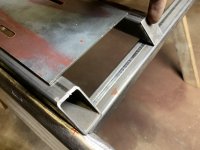
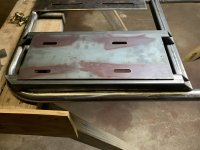
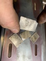
Added a mount for the engine plate. It needed to be up an inch to clear the torque converter. I made some 45 degree cuts on the ends to make it look cleaner. I also cut some rectangles to keep the insides from rusting ( maybe?? ) I am holding one on in this picture:

Engine_plate_riser_with_me_holding_an_endcap_on.JPG

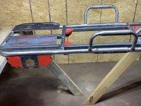
This is a side view of the frame with everything sitting how it will be welded on. Some of it is held on with magnets at the moment.

image_50401025.JPG

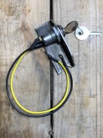
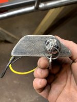
The only thing I am doing to the front currently is moving the kill switch from the engine to the front. I found this tractor 'ignition' at tractor supply that I'm going to wire in between the ground:

Here is what it will look like
Me_Holding_the_tractor_ignition_killswitch_on.JPG

Still waiting on my seat hardware so I can't put the seat on yet. =(
 

Attachments

  • Tractor_ignition_killswitch.JPG
    Tractor_ignition_killswitch.JPG
    2 MB · Views: 1
  • SquareTubingAttachedToRoundTubing.JPG
    SquareTubingAttachedToRoundTubing.JPG
    1.7 MB · Views: 1
  • Engine_MountTopView.JPG
    Engine_MountTopView.JPG
    1.9 MB · Views: 0
  • EngineMountFancyView.JPG
    EngineMountFancyView.JPG
    1.8 MB · Views: 0
  • RectangularEndCaps.JPG
    RectangularEndCaps.JPG
    1.5 MB · Views: 0
  • CloseupRearLayout.JPG
    CloseupRearLayout.JPG
    2.2 MB · Views: 0
  • StraightOnKillswitch.JPG
    StraightOnKillswitch.JPG
    1.4 MB · Views: 0

Rat

Well-known member
Messages
1,750
Reaction score
1,284
Location
SW Virginia
Hey you guys. Merry Christmas!

I have a mini update:

Added a mount for the engine plate. It needed to be up an inch to clear the torque converter. I made some 45 degree cuts on the ends to make it look cleaner. I also cut some rectangles to keep the insides from rusting ( maybe?? ) I am holding one on in this picture:

View attachment 144298

This is a side view of the frame with everything sitting how it will be welded on. Some of it is held on with magnets at the moment.

View attachment 144299

The only thing I am doing to the front currently is moving the kill switch from the engine to the front. I found this tractor 'ignition' at tractor supply that I'm going to wire in between the ground:

Here is what it will look like
View attachment 144301

Still waiting on my seat hardware so I can't put the seat on yet. =(
Nice work, I prefer to cut my square tube so I can cap the ends by folding it over and only weld 3 sides instead of a separate piece.
For round tube since it can't be done that way so easily I like to use a fender washer, and plug it with multiple quick zaps to build it in, knock it all down smooth with the grinder.
 

NEKrone

Member
Messages
26
Reaction score
26
Location
Michigan (LP) , USA
Nice work, I prefer to cut my square tube so I can cap the ends by folding it over and only weld 3 sides instead of a separate piece.
For round tube since it can't be done that way so easily I like to use a fender washer, and plug it with multiple quick zaps to build it in, knock it all down smooth with the grinder.
Thanks for the kind words! That is a good idea for the square tube ends. The end caps I made were definitely an afterthought. I wasn't sure what the 'industry standard' way was 🤷‍♂️ but I'm definitely having a ton of fun experimenting.

Everything is getting welded tomorrow and then I'll chop off the handlebars and move them back and angle them down more to clear the seat and then add a hoop behind the seat attached to those handlebars for lateral reinforcement.

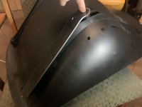
The seat tilts back a little farther than I'd like so I am going to remove the gas tank attached to the engine and mount it to the hoop I am adding.

This is the seat I have. I wanted something that would cup the driver so I wouldn't be tossed out in a hard turn.

Any tips on how to properly align the engine to the rear axle before I weld would be much appreciated. My plan is to measure how far each bearing hanger is from the front of the kart and make sure they are the same length and then eyeball the engine and see if it's square with the axle. ( ??? )

I did notice because the frame was stretched that the rear is about 1/16th of an inch wider than the front. One side is very straight but the other side is slightly turned to the outside but I figured that 1/16th would not require any kind of compensation.

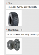
I did have a question about front tires. I was going to get these tires from bmikarts but the website says the bearings are 3 inches apart and my spindles are barely over three inches. I am not sure if I'm measuring from the correct spot so are these not going to fit? If I got these they would match the rears.

Front_Tire_Options.PNGFront_Rim_Specifications.PNG
 

Attachments

  • Spindle_Measurement.JPG
    Spindle_Measurement.JPG
    1.9 MB · Views: 6

NEKrone

Member
Messages
26
Reaction score
26
Location
Michigan (LP) , USA
I got everything welded in place. Got the engine mount tacked. The rear axle is not square with the rear end but it is reasonably square with the front end. From the center of the rear axle to the end of the front of the kart, one side was 1/16th of an inch farther away than the other.


driverSeatUnderTray.JPG

Some of the welds don't look too well but some are hard to get at with the angle grinder I'm using so I may just remove the slag from the welding and just paint the welds however they end up looking. :unsure:

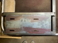
This is the engine mount. I cut a chunk out of the frame on accident while removing the old axle so angle iron was welded to the underside and outside to cover it. One was added to both sides just cuz.

egineMountTacked.JPG

I finally received the seat mount hardware and got my seat to fit it. The rear screw holes on the seat are angled so I made an angled adapter so I could attach the seat to the adapter and the adapter to the seat hardware.

I had some wheels donated to me for the fronts. I don't know what they came off of. 🤷‍♂️

I also tried to see if it was comfortable with the seat on it and realized the steering wheel would be too low so I added 7 inches to it.
frameSupportedByWheels.JPG

I'm ok with it so far. Next I need to add the mount for the brake caliper and The hoop at some point.
 

Attachments

  • eightyPercentAssembled.JPG
    eightyPercentAssembled.JPG
    472.2 KB · Views: 8

Rat

Well-known member
Messages
1,750
Reaction score
1,284
Location
SW Virginia
I got everything welded in place. Got the engine mount tacked. The rear axle is not square with the rear end but it is reasonably square with the front end. From the center of the rear axle to the end of the front of the kart, one side was 1/16th of an inch farther away than the other.


View attachment 144416
The real question would be is the axle square to the frame? Is it centered?
If not square, 1/16 probably isn't enough to make a handling problem, but it may cause accelerated tire wear... which is already a problem with a live axle on paved surfaces.

1/16 off center isn't enough than an extra washer or two cant offset the closer wheel and make center.

If it's just 1/16 in the frame rails overall... who cares.
 

hardcorps

Member
Messages
96
Reaction score
83
If you put a person in that kart then the frame will flex at least 1/16" somewhere. Since you're doing all the work I would square the axle to rear end of the kart frame and tweak the front frame 1/16" or so IF you're worried about it. I don't think a sixteenth is anything to worry about.
Dislaimer: I am not a go kart scientist.
 

NEKrone

Member
Messages
26
Reaction score
26
Location
Michigan (LP) , USA
The real question would be is the axle square to the frame?

It's hard to say. The frame warped while the center section was being welded on 😭. The frame is not very square so I hoped if I tried to make the rear wheels square to the front wheels that it would at least drive straight. Had to grind off the torque converter screw hole cover nearest the sprocket off so it could wiggle enough to be square on the axle. :unsure:
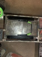
Since my phone died before I could get a photo of the seat, here is some more pictures!

The seat slider handle was too big and wide so I cut them down to make a mini handle. Tape is holding it together until I can weld it in a few minutes.

shortenedSeatHandle.JPG

This here is the adapter I made for my seat. the front hole will bolt through the seat and the seat sliding hardware while the rear will bolt to the seat and then to the hardware separately.
SeatAdapters.JPG
This is showing the angled mounting holes on my seat with my adapter set on it.
showingSeatHolesAreAngled.JPG
 

Rat

Well-known member
Messages
1,750
Reaction score
1,284
Location
SW Virginia
It's hard to say. The frame warped while the center section was being welded on 😭.
Using an internal reinforcement stub for those butt welds, and a ratchet strap (or a few of them) work miracles to prevent that, so does a length of unmolested 1.5× angle iron and a couple (or a few) C-clamps.

With square tube like that it can be tricky to find a tube that fits inside, but (for but welding any tube) I like to drill a peephole all the way through about an inch back from the end, slide or pound in a 3" section, tack it through one peephole, tap it square to the tube, tack the other, check square and correct if needed, fill the peepholes in...rinse and repeat for the section being added.

Exhaust is the only thing I don’t use this method for, but if it's not square/straight I just find the outside of the off angle, slice a bit more than half through with an 0.045 cut-off, force it shut enough to straighten and burn it shut, repeat as necessary for desired angle or straightness
 
Last edited:

Hellion

Moderator
Messages
8,522
Reaction score
3,618
For the steering wheel, maybe turn the frame over and support it on saw horses then try multiple applications of Liquid Wrench, WD40 or Angel Piss 😆 (Kroil) to see if that and gravity will penetrate and loosen the rust. Make sure the cross bolt is off.
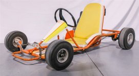
Try differential heating but just apply high heat (blowtorch) to the shaft and not the wheel (since it's plastic and will melt). Go easy and another trick is to use the wax method. Get the shaft near the steering wheel mount (the wheel has a steel insert, correct?) smoking hot but not red hot, then apply a candle to the joint. The candle melts and the hot liquid wax wicks into the joint between the steering wheel and often does the trick. .....there's guys on Youtube who swear by it.

That wheel definitely needs to be turned over for "proper" appearance like on this Orange Krate...

64CA84A9-206B-4CEC-B2A8-13EB570B886B.jpeg
 
Top