my mini chopper

Status
Not open for further replies.

mckutzy

Well-known member
Messages
8,353
Reaction score
107
Location
bc, canada
I did some more work to day just finished up about a couple of hours ago.
Oh what I did last day,

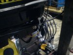
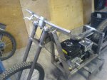
I got the bars on and the throttle hooked up for testing.

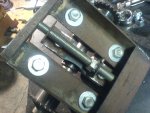
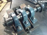
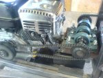
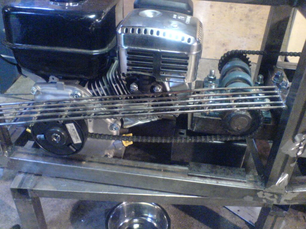
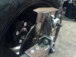
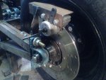
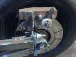
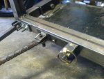
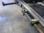
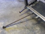
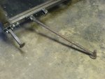
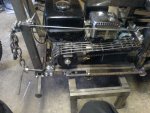
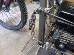
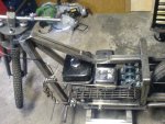
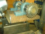
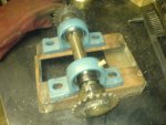
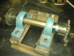
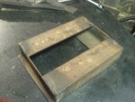
Today I think I have found out a way to get the chain to work around the the frame. I made a "shelf" that will be attached to the frame and the jackshaft will be mounted on it, with a tensioner pillow-block in the middle(not shown, I have to get another one). I havent figured out if I should weld the shelf onto the frame or bolt it on, it is shown clamped on for display.


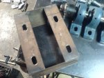
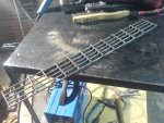
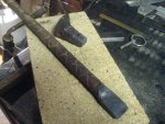
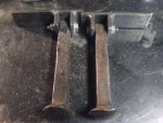
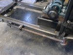
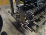
here's what it looks like off the bike...


The chain will clear on both sides and a little room to adjust the tracking of the chain for alignment. Over all I am happier now that I figured out what to do about this chain deal. Defiantly goes to show, measure twice and check and then check again if your setup is correct before carrying on.
 

Attachments

  • DSC01141.JPG
    DSC01141.JPG
    455.2 KB · Views: 1
  • DSC01158.JPG
    DSC01158.JPG
    469.8 KB · Views: 1
  • DSC01167.JPG
    DSC01167.JPG
    436.7 KB · Views: 1
  • DSC01168.JPG
    DSC01168.JPG
    486.6 KB · Views: 1
  • DSC01163.JPG
    DSC01163.JPG
    457.4 KB · Views: 1
Last edited:

acg23

Member
Messages
196
Reaction score
1
Location
bay area
looks nice mann. just gotta get a seat for it.. are those ur welds on the jackshaft sprocket??
 

mckutzy

Well-known member
Messages
8,353
Reaction score
107
Location
bc, canada
thanks man. Yes those are one of my first tig welds on my bike. Up untill this project I had not done any tig welding before. I had however done some O/A welding, which is very similar but without much of the excess heat to melt metal. the motions are much the same so that was some good practice for this. A steady Hand/eye coordination are key for this type of welding.
 

acg23

Member
Messages
196
Reaction score
1
Location
bay area
not badd for first time! that explains it. lol. tig is by far my favorite way too weld. i hear that. i work as a stainless steel tig welder
 

mckutzy

Well-known member
Messages
8,353
Reaction score
107
Location
bc, canada
I might build/convert my mig to tig, or get a old 220 stick welder and get a tig setup for that.
An Old welder guy I met once, showed me a tig setup he made that attaches to his dc stick welder. He said one time he needed to get up high at this one SS pipe in a brewery, he took a bottle of gas on his backpack rig and the ground clamp, hooked up the torch end and set his machine on the ground, climbed up and welded these pipes. very simple, scratch start and of course no pedal but a simple and effective setup. Have to adjust manually but this how they apparently did back in the day.
 

bighead

New member
Messages
4,022
Reaction score
50
Location
Pacific Northwest USA
In the pic below next to the aluminum bar riser. I would weld a stopper on each side of the bar riser. You only have one so it could spin. If you welded a stop your riser could not spin on the single bolt.

great work by the way. looks killer...


mckutzy

Well-known member
Messages
8,353
Reaction score
107
Location
bc, canada
oh ya, I had forgotton about that awile ago, I am going to weld a plate on the front of the riser to stop it from spinning, I think a light mount will go there to break up the look a bit. It is actually steel. It has some galvanizing on it so the look is off a bit, it was mostly ground off but there is always zinc sticking to galvanized pipes and bars. This bar was a drill rod for these worm drill thingy. They drill this big auger looking thing into the ground and then then weld the ends to rebar reinforcement for a cement pads they use for buildings and houses. This was just a end scrap with the hole drilled through it, saved time drilling the bar hole.
 

mckutzy

Well-known member
Messages
8,353
Reaction score
107
Location
bc, canada
Well the last few days were a busy one and I determined to try to get this one finished. Last weekend , I got the holes marked and drilled for the jack shaft, assembled the tensioner and the shaft parts. I was so happy that this worked, the tension bolt spins freely and moves the shaft forward.


So after I had put that together, I set up for mounting the jack-shaft bracket to the frame.
I had spent most of the week trying to figure out what method of mounting, weather to weld it to or bolt it to the frame. I later concluded to bolt it on, sighting that it might be a ***** to to take apart later or just to do finishing work without that big thing in the way.

With the J/S off and disassembled, I also removed the engine, forks and the rear tire so that I could get at the frame to set up to drill. I clamped, measured and then drilled. I had bought some nuts/bolt/washers for this but I bought the wrong length, so after drilling I just used them as a basis for the length of chains required.
The other day I got new bolts as I was off .5", I forgot my list of sizes when I went out, I went from memory and guessing instead.
Today I replaced the new proper length bolts, I also drilled the frame and motor plate for the front tensioner bolt.
So by mid day I had achieved this far.

and another with the motor running

This is quite a feat in my eyes, I was so tempted to giver a run out in the alley, but I hadn't got the brake situation dealt with yet. later today I did get a brake bracket made, I also need some more bolts to mount it, Ill get that tomorrow. I will also post pic of the caliper bracket, I was just on a mission and went with it. So didnt take any pics of it yet.
 

Attachments

  • DSC01179.JPG
    DSC01179.JPG
    456.7 KB · Views: 1
  • DSC01178.JPG
    DSC01178.JPG
    476.8 KB · Views: 1
  • DSC01177.JPG
    DSC01177.JPG
    466.8 KB · Views: 1
  • DSC01175.JPG
    DSC01175.JPG
    426.3 KB · Views: 1
  • DSC01180.JPG
    DSC01180.JPG
    466.8 KB · Views: 1
  • DSC01183.JPG
    DSC01183.JPG
    416.1 KB · Views: 34

r_chez_08

Should be in the shop...
Messages
4,827
Reaction score
12
Location
Cornwall, UK
Looking good, but why so overkill on the js bearings, 2 would be sufficient IMO.
Also the chain looks a little slack. How much play does it have? 1/4" to 1/2" is good. Might just look that way cos the motor is running.
 

mckutzy

Well-known member
Messages
8,353
Reaction score
107
Location
bc, canada
The middle pillow block is a tensioner for the rear chain. I went with the 1" shaft cause I originally bought a bunch of them cheap, then with the j/s redesign I just went with it. The front chain has a about .5" max slack, if there is a need to Ill take out a link, I have more room with the front tensioner on the motor plate. Thanks for noticing.
 

mckutzy

Well-known member
Messages
8,353
Reaction score
107
Location
bc, canada
I got my brake caliper bracket figured out. My caliper is a different design than some other typically seen. It has the actuator at the 12 and 6 o'clock positions most I have seen are able at the 3 and 9, although this made it a bit easier to use in the end, the method of mounting made it a trouble for me for since I got it a year or so ago.


Today I made a clutch/chain guard from some rod I found. Actually we just had an election here in Canada, and I went and grabbed a bunch of the election pickets on the side of the road, they used a 3/16 cold finished steel rod. about 8.5' long, so yay for free materials.


A friend of mine had given me a bunch of Rail spikes, Ill be using them for foot pegs and maybe the brake pedals aswell. Here's an example of what Im talking about.
 

Attachments

  • DSC01192.JPG
    DSC01192.JPG
    473.5 KB · Views: 1
  • DSC01193.JPG
    DSC01193.JPG
    499.9 KB · Views: 2
  • DSC01191.JPG
    DSC01191.JPG
    484.9 KB · Views: 2
  • DSC01187.JPG
    DSC01187.JPG
    477.6 KB · Views: 1
  • DSC01194.JPG
    DSC01194.JPG
    503.4 KB · Views: 2
  • DSC01195.JPG
    DSC01195.JPG
    509.6 KB · Views: 1

mckutzy

Well-known member
Messages
8,353
Reaction score
107
Location
bc, canada
I have been busy, I have made a few things and Im almost ready for a test ride.

The other day I made some pegs out of rail spikes. These nails are carbon steel, some are and some are not. With the steel a bit toughter to drill, some may have annealed before from them being hammered, or bent, just in the track so long had hardened them a bit. It was a bit of a struggle but I gotter done.


Yesterday I had started to make a kickstand and I finished it today. I went out to the Tim Hortons(this is our nations most popular coffee chain, its better than starbucks, :wai:hehehe) and on my walk back I found a piece of 5/8" rebar about 17", I grabed it, as with most of my bike is composed of found and scrap materials, I thought this would accent it nicely.
So after a good think on how to use it, I started forging out the end to make it a bit thinner and wider, so it is 1"x 3/4"x 1/4" on the end. I also took a rail spike and cut the head off about 1.5" long, this will form the foot of the kick stand.


After the arm and foot were cut, I went ahead on the mount. I thought on some ways for the mount to have a spring return for the arm but in looking for some other bits, I had found a spring retaining pin( I have no idea what there called, I know they use them on tractors) found it walking to work one day years ago.
I decided that I am not going to be riding it all the time and although it would be a convenience for the kickstand to be sprung, I thought hey Ill pin it when not in use, it has a spring to keep it in place when moving or storing it. This is what I came up with.


Here it is closed. http://i248.photobucket.com/albums/gg182/mckutzy/bike/DSC01219.jpg


So after the mount was made, the foot needed to be fitted on.
With the mount drilled and bolted to the frame. I put on the arm and allowed the bike to rest on the ground see how it leaned. Looks good. I lifted the bike and put the Nail head under the end of the arm, adjusted the position so it sat right, tacked it on, then carefully lifted and blocked the bike, I removed the arm.
With these nails being carbon steel, there is a little trick needed to make a decent weld stay on without breaking or cracking. The metals have to be heated hot before in order to weld effectively.
I have a propane/mapp gas bernzomatic brazing torch meant for plumbing, thats also what I used to forge the kickstand arm. I heated the end of the kickstand about a cherry red, it needs to be hot, then welded all around.
I went to Tims again and allowed the part to cool slowly. After brushing, here's what it looked like.
 

Attachments

  • DSC01212.JPG
    DSC01212.JPG
    500 KB · Views: 1
  • DSC01204.JPG
    DSC01204.JPG
    472.6 KB · Views: 1
  • DSC01198.JPG
    DSC01198.JPG
    499.3 KB · Views: 1
  • DSC01223.JPG
    DSC01223.JPG
    445.8 KB · Views: 1
  • DSC01215.JPG
    DSC01215.JPG
    469.4 KB · Views: 1
  • DSC01216.JPG
    DSC01216.JPG
    440.1 KB · Views: 1
  • DSC01219.JPG
    DSC01219.JPG
    412.5 KB · Views: 1
  • DSC01222.JPG
    DSC01222.JPG
    414.1 KB · Views: 1
  • DSC01214.JPG
    DSC01214.JPG
    409.9 KB · Views: 1

mckutzy

Well-known member
Messages
8,353
Reaction score
107
Location
bc, canada
Here is some more of the kickstand.


Attachments

  • DSC01224.JPG
    DSC01224.JPG
    438.1 KB · Views: 1
  • DSC01218.JPG
    DSC01218.JPG
    474.8 KB · Views: 1
  • DSC01217.JPG
    DSC01217.JPG
    416.8 KB · Views: 1
  • DSC01213.JPG
    DSC01213.JPG
    432.3 KB · Views: 1

mckutzy

Well-known member
Messages
8,353
Reaction score
107
Location
bc, canada
So now that I am mostly done, all I need to is the brake linkage with pedals or something, and a seat.
I had done some work with the brake a week ago. I didnt take any pics yet, but I will soon. It was just a rod that went from the brake arm to the seat post with a bend and a gusset to reinforce the bend. It needed a bend in order to clear the frameand motor , but I redirected where I will need it to be for the forward pivot mounts will be located. I know this sounds confusing but it will be clear soon, I just need to get some custom mounts made first.
 

landuse

Moderator
Staff member
Messages
18,740
Reaction score
506
Location
Pietermaritzburg, South Africa
That bike is really nice. I am just a little concerned about that kickstand. It looks a little week where it connects to the frame. I was also thinking it is a bit long, and that could create a lot of leverage on the weld to the frame. Does it work OK?
 

mckutzy

Well-known member
Messages
8,353
Reaction score
107
Location
bc, canada
It does seem a little long and the angle of bike in the pic look like its about to fall over, but no.. it works. There is a cap on the end of the mount so the arm doesnt flip all the way forward, that reinforces the joints.

I will however be upgrading all the 1/4" hardware to 5/16" bolts, it was all I had and after looking at it a wile I though Ill use some bigger bolts for the pegs, kickstand and what ever else later on.
 

mckutzy

Well-known member
Messages
8,353
Reaction score
107
Location
bc, canada
Well Iam about done now except for a seat and maybe some grips. My progress as of late.


I also made a kill switch that I think is pretty cool, a great idea from Gator, on this thread http://www.diygokarts.com/vb/showthread.php?t=11516


I have to get a helmet and giver a try when the weather is better, lately its the craps.

Its Been about three years in the making of this bike, and at least a 150hrs.
I was meaning to mention, on this project the things I bought were just the engine, hardware, drive train, shafting and the brake caliper. About $200 cost, but it would have been about $350 if I had bought all of the materials.
 

Attachments

  • DSC01226.JPG
    DSC01226.JPG
    501 KB · Views: 1
  • DSC01227.JPG
    DSC01227.JPG
    485.3 KB · Views: 1
  • DSC01230.JPG
    DSC01230.JPG
    478.2 KB · Views: 1
  • DSC01231.JPG
    DSC01231.JPG
    502.5 KB · Views: 1
  • DSC01232.JPG
    DSC01232.JPG
    420.4 KB · Views: 1
  • DSC01233.JPG
    DSC01233.JPG
    486.8 KB · Views: 1
Status
Not open for further replies.
Top