hankll
New member
Just bought this Murray for my Grandson for his 11th BD.....has original Tec 6 hp engine, which except for a little cold natured action it runs good when warmed up. The people who had it before traded it to the guy we bought it from, and he was just looking to get his money. $175 was a good price, I thought, for a running kart. It has had some welding done on the steering and I think it is not repaired properly. It doesn't turn right very far, and does better turning left, but still isn't turning like it should. It also has the camber on both steer spindle axles swagged out at the bottom. The bearings seem tight, and smooth, and I think the swag is in the wheel spindles outward of where they come through the spindle yoke that have the kingpin running through it. The king pins are tight and don't have any looseness where it is attached the axle, and I don't see any swag in the axle. It is welded into the frame, so it is solid.
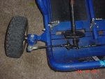
What I think I see, is the people when they welded the pivot where the steering linkages attach, are mounted on a single stud. When the wheels are turned right, it doesn't throw the right wheel far enough right, while the trailing left wheel looks about like it should on the steering angle. When turning left the pivot throws the longer of the steering links further left, but still not quite enough as I think it should and the right trailing steer wheel isn't trailing into the turn enough either, yet is better than the right turn when the left steer wheel is in the trailing position into the turning diameter.
I think the steering column should have two locations for the two steer links to mount separately. The way I envision that action, it would throw the trailing steering better , and when that same wheel becomes the leading steer wheel it would throw it into a tighter diameter turn radius.
Any which way, the repairs they did, have it messed up in the turning part of it. I know what the steering angles should look like based on looking at my Murray riding lawnmower. I don't have an owners manual or even a parts manual. So I don't know how or what the steering links are hooked to, or how they should be hooked up at the base of the steer column.
The model number is GT60303x92D
The photo is my Backberry, so it isn't a very good shot. I''ll try to get out there when He isn't running it, and use my Sony camera, and get some better closeups of the links and steering column and angles produced in the turns.
Any help or even a phot of an original set up on a Murray Kart, a diagram closeup of what it should look like so I can get the steering fixed up before he wears out the tires.
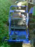
The left photo is what I bought, we didn't get the top roll bar part....like the one I copied from here. I just wanted a photo of the correct version so you could visualize better, what I had. We are supposed to be able to get the original roll cage parts from that previous owner that did all the welding.
What I think I see, is the people when they welded the pivot where the steering linkages attach, are mounted on a single stud. When the wheels are turned right, it doesn't throw the right wheel far enough right, while the trailing left wheel looks about like it should on the steering angle. When turning left the pivot throws the longer of the steering links further left, but still not quite enough as I think it should and the right trailing steer wheel isn't trailing into the turn enough either, yet is better than the right turn when the left steer wheel is in the trailing position into the turning diameter.
I think the steering column should have two locations for the two steer links to mount separately. The way I envision that action, it would throw the trailing steering better , and when that same wheel becomes the leading steer wheel it would throw it into a tighter diameter turn radius.
Any which way, the repairs they did, have it messed up in the turning part of it. I know what the steering angles should look like based on looking at my Murray riding lawnmower. I don't have an owners manual or even a parts manual. So I don't know how or what the steering links are hooked to, or how they should be hooked up at the base of the steer column.
The model number is GT60303x92D
The photo is my Backberry, so it isn't a very good shot. I''ll try to get out there when He isn't running it, and use my Sony camera, and get some better closeups of the links and steering column and angles produced in the turns.
Any help or even a phot of an original set up on a Murray Kart, a diagram closeup of what it should look like so I can get the steering fixed up before he wears out the tires.
The left photo is what I bought, we didn't get the top roll bar part....like the one I copied from here. I just wanted a photo of the correct version so you could visualize better, what I had. We are supposed to be able to get the original roll cage parts from that previous owner that did all the welding.
Attachments
-
 blackberry_photo_editor_ultimate_free(24).JPG268.6 KB · Views: 23
-
 f775_1.jpg25.6 KB · Views: 24